
Basic information
1. Before disassembling the carburetor, make sure that the ignition timing is set correctly. Spark plugs must be clean and their spark gap properly adjusted. The damper actuators must be properly adjusted and the air filter must be clean. Refer to the relevant paragraphs if necessary Chapters 1A and this chapter. If the engine runs very rough, first check the valve clearances as described in Chapter 1A, and then check the compression as described in Chapter 2A.
2. If, after eliminating all other possibilities, the carburetor is found to be faulty, inquire about the price and availability of carburetor replacement parts and repair kits before deciding what to do. Replacing the entire carburetor may be a better solution than trying to repair it.
3. A carburetor repair kit usually contains parts that are either worn out during operation and damaged during disassembly. For example, gaskets, washers, seals, diaphragm jets, etc. Before purchasing individual parts, check with the supplier to see if the kit required for your carburetor is available. Note that in most cases it will be enough to disassemble the carburetor and clean the jets and channels with carburetor cleaner.
4. The remainder of this paragraph describes the repair and replacement of major carburetor components.
Replacement Parts
Air damper actuator
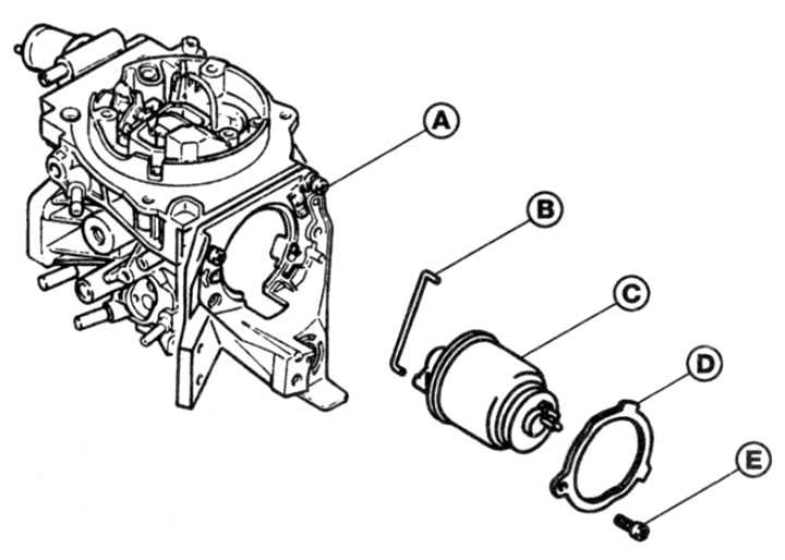
5. Remove the air cleaner as described in paragraph 2.
6. Disconnect the plug on the block of the actuator.
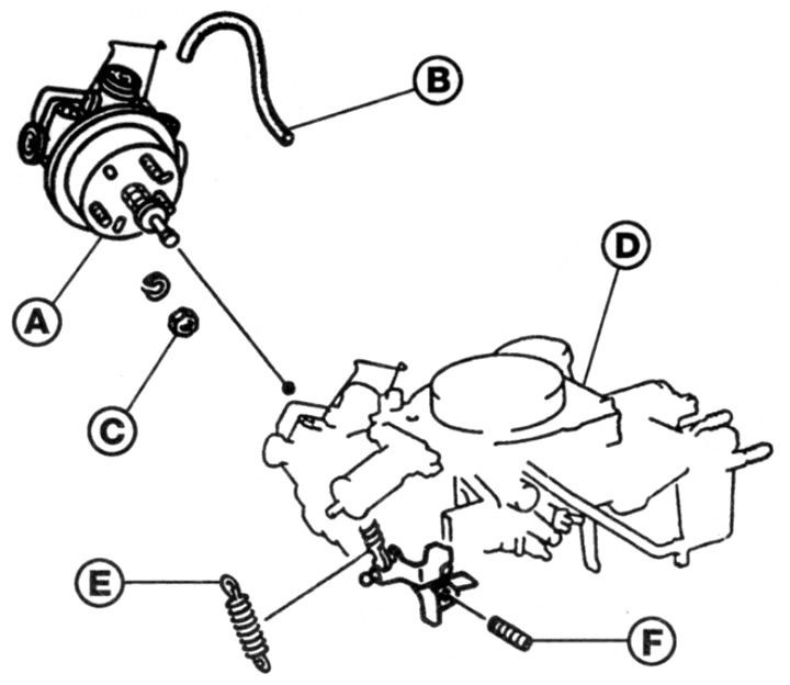
7. Loosen the screw and remove the fastening ring (see fig. 9.7).
Pic. 9.7. Choke Actuator - Pierburg Carburetor
A Carburetor body
To Rod
C mechanism body
D Attachment ring
E Screw
8. Disconnect the rod from the choke lever, then rotate the mechanism housing to disengage the retaining paley and remove the mechanism from the carburetor.
9. Installation is carried out in the reverse order.
Throttle mechanism
10. Remove the air cleaner as described in paragraph 2.
11. Disconnect the wire plug from the mechanism block. Disconnect the vacuum hose from the connector on the side of the mechanism.
12. Turn away three nuts of fastening and remove washers (see fig. 9.12).
Pic. 9.12. Throttle control mechanism - Pierburg carburetor
A Housing
B Vacuum hose
C Nuts
D Carburetor body
E Return spring
F Adjusting screw
13. Remove the mechanism from the carburetor.
14. Installation is carried out in the reverse order. Note that the clearance between the actuator pushrod and the stop screw on the throttle lever must be between 1.5 and 2.5 mm.
Cooling system sensor
15. The coolant sensor is located on the cylinder head at the front end of the engine (accessory drive belt side) (see fig. 9.15).
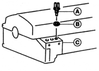
Pic. 9.15. Coolant sensor location
A Sensor
The Seal
C Cylinder head protrusion
16. Disconnect the wire plug from the sensor block.
17. Make sure the engine is cool. Then briefly open the expansion tank cap to relieve pressure in the cooling system.
18. Turn out the gauge from a head of cylinders and remove a sealing ring. Be prepared for some of the coolant to spill - place rags on the surrounding surfaces to catch the liquid.
19. The coolant sensor can be tested by heating it in a glass of water along with a thermometer. Using an ohmmeter, measure the resistance of the sensor at various temperatures as it warms up and compare these results with the data given in the Technical Data section
20. Install the sensor in reverse order. When finished, start the engine and check that there are no leaks from under the sensor.
Electronic control unit
Caution: Electronic control unit (ECU) contains parts that are sensitive to the level of static electricity generated by humans during normal operation. With the harness connector disconnected, loose contacts are free to conduct static electricity to these parts, rendering them inoperable or even damaging them. Damage may not be noticeable and not immediately manifest. Costly repairs can be avoided by following these basic rules:
- A) Hold the ECU only by the body; do not touch the block contacts with fingers or tools.
- b) When working on the ECU, ground yourself from time to time by touching metal objects such as unpainted water pipes. This will allow the static electricity to drain from your body.
- V) Do not leave the ECU disconnected longer than necessary for operation.
21. The electronic control unit is located behind the engine compartment on the right side of the bulkhead under the cover.
22. Disconnect the negative battery terminal.
23. Unfasten the latches and remove the cover.
24. Press the metal holders on the electronics box, then disconnect the connector. Pull the block perpendicularly to avoid bending the pins inside the connector.
25. Turn out screws and remove the control block.
26. Installation is carried out in the reverse order.