
Note: Adjusting the clearances in the valve drive mechanism must be carried out on engines without hydraulic tappets. on engines built before October 1984. Checking and adjustment can be performed both on a cold and hot engine.
1. Remove the camshaft cover as described in Chapter 2A.
2. Disconnect the low voltage plug on the electronic ignition control unit (see Chapter 5B).
3. Using an appropriate wrench, turn the crankshaft at the crankshaft pulley bolt in the normal direction of rotation so that the intake and exhaust valve cams of the first cylinder point down from the rocker arms.
4. Using a flat feeler gauge with a thickness corresponding to the recommended clearance, check that the feeler gauge is pulled between the valve stem and rocker arm with little effort (see fig. 28.4). Please note that the intake valves are located in the cylinder head on the intake manifold side, and the exhaust valves on the exhaust manifold side. The intake and exhaust valve clearances are different.
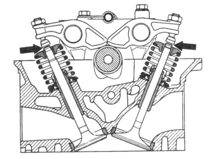
Pic. 28.4. Checking the gaps in the valve drive mechanism between the valve stem and the rocker arm with the camshaft cams facing down
5. If adjustment is required, loosen the locknut, turn the rocker arm adjusting screw to the desired clearance, and tighten the locknut while holding the adjusting screw stationary.
6. When both valve clearances of cylinder #1 are set, turn the crankshaft to set the lobes for the next pair of valves (cylinder number 2) down, and in the same way adjust the clearances of these valves. Repeat steps for cylinders 3 and 4.
7. When finished, install the camshaft cover as described in Chapter 2A.