
Front axle
Executive cylinder
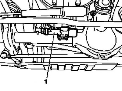
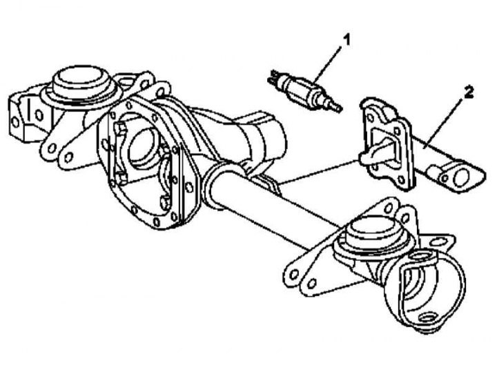
Installation details of the slave cylinder (1) front axle differential lock drive
Adjustment of the executive cylinder (1) front axle differential lock drive
1 - Executive cylinder
2 — Sensor-switch pressure
1. Disconnect from slave cylinder assembly (1) hydraulic line, - plug the open ends of the line and fitting assembly immediately to prevent leakage of brake fluid.
2. Loosen the union nut and disconnect the electrical wiring.
3. Mark the installation position of the cylinder (1) relative to the bridge.
4. Turn out fixing screws and remove the cylinder (1).
5. Install the cylinder in its regular place in accordance with the landing marks applied during the dismantling process.
6. If the cylinder was disassembled (see Section Dismantling and assembling the slave cylinder of the differential lock drive) or replacement of components of the differential lock mechanism (see below), make appropriate adjustments (see below).
7. Screw into the cylinder (1) pressure switch (2) and tighten it with the initial force.
8. Fix the cylinder (1) on the axle housing so that it remains possible to adjust its position.
9. Activate the cylinder and lock the dog clutch.
10. Correct the position of the cylinder so that it rests against the clutch - when released, the cylinder should not move back under the influence of the force developed by the internal spring.
11. Tighten the cylinder to the required torque.
12. Completely tighten the pressure switch.
13. Restore original wiring and hydraulic line connections.
14. In conclusion, bleed air from the hydraulic path of the differential lock actuator (see Section Removing air from the hydraulic path of the differential lock drive).
Locking mechanism
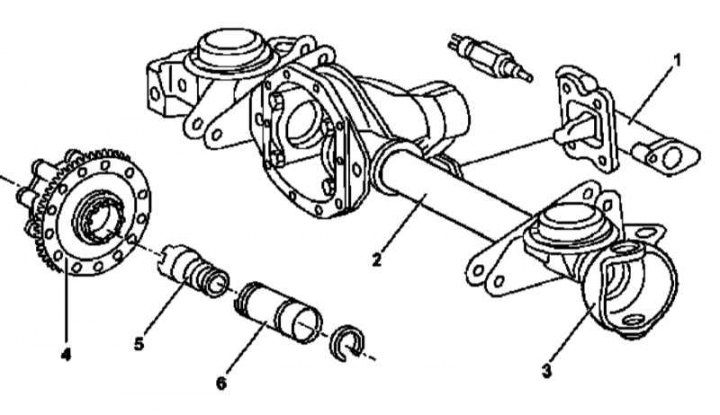
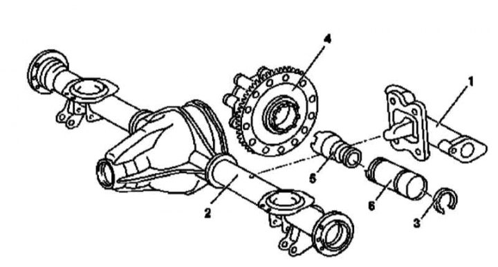
Installation details of the components of the front axle differential lock mechanism
1 - Executive cylinder; 2 - Sleeve of the crankcase of the bridge; 3 - Hinged casing; 4 - Assembling the differential with the driven gear of the final drive; 5 - Clutch of the switching mechanism; 6 - Switch mechanism tube
1. Remove the slave cylinder (1) (see above).
2. Remove the hinge cover (3) complete with drive shaft (see Section Removal and installation of drive shafts of the forward bridge).
3. Remove differential complete with final drive gear (4) (see Section Removal and installation of assemblies of cross-axle differentials with driven gears of main gears).
4. Remove shift clutch (5), slightly pulling it in assembly with a tube (6), after which I unhooked it.
5. Pick up the handset (6).
6. Remove from tube (6) polyamide rings.
7. Thoroughly wipe the removed components Replace the failed components.
8. Install the polyamide rings, having previously lubricated their rubbing surfaces.
9. Install shift tube (6).
10. Hook up the clutch (5) and push together with the tube until the installation socket appears in the hole in the sleeve of the axle housing (see illustration below).
11. Install differential assembly (4).
12. Install the hinged cover (3) complete with drive shaft (see Section Removal and installation of drive shafts of the forward bridge).
13. Install slave cylinder (see above).
Rear axle
Executive cylinder
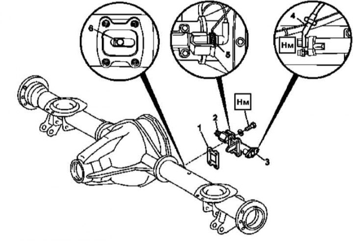
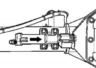
Installation details of the rear axle differential lock slave cylinder
1 - Sealing gasket; 2 - Pressure sensor-switch; 3 - Executive cylinder; 4 - Hydraulic line; 5 - union nut; 6 - Mounting socket
Adjustment of the executive cylinder (1) rear axle differential lock
1. Disconnect from slave cylinder assembly (3) hydraulic line (4), - Seal the open ends of the line and fitting immediately to prevent leakage of brake fluid.
2. Loosen the union nut (5) and disconnect the wiring.
3. Mark the installation position of the cylinder (3) relative to the bridge.
4. Turn out fixing screws and remove the cylinder (3).
5. Align the installation slot (6) shift clutch in the center of the opening in the crankcase sleeve.
6. Install the cylinder (3) to its regular place in accordance with the landing marks applied during dismantling - do not forget to replace the seal (1). Screw in the fixing bolts - the shift lever should fall into the mounting socket of the tube, while it should be possible to adjust the position of the cylinder.
7. Apply hydraulic or pneumatic pressure to actuate the cylinder, then move it against the dog clutch (arrow), - simultaneously rotate the axle shafts until the differential lock is activated.
8. Tighten the mounting bolts to the required torque, then release the hydraulic/pneumatic pressure.
9. Rotate the axle shafts to make sure that the differential lock is working.
10. Restore original wiring and hydraulic line connections.
11. In conclusion, bleed air from the hydraulic path of the differential lock actuator (see Section Removing air from the hydraulic path of the differential lock drive).
Locking mechanism
Installation details of the components of the front axle differential lock mechanism
1 - Executive cylinder; 2 - Sleeve of the crankcase of the bridge; 3 - Polyamide ring; 4 - Assembling the differential with the driven gear of the final drive; 5 - Clutch of the switching mechanism; 6 - Switch mechanism tube
The procedure is the same as described above for the front axle, corrected for the lack of a hinged casing.