
Gear lever
Removing
1. Pull the shift lever cover off the center console and twist it up over the lever.
2. Using a screwdriver, pry the circlip out of the hole in the selector lever tube and remove the circlip (see fig. 3.2).
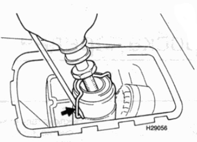
Pic. 3.2. Pry off the snap ring from the tube of the gear selector lever with a lever
3. Pull the lever out of the tube.
Installation
4. Installation is carried out in the reverse order. Make sure the spring ring is in the correct position.
Gearshift unit
Removing
5. For better access to parts, apply the parking brake, then raise the front of the vehicle and support it on jack stands (see "Vehicle lifting and jacking up").
6. Working from underneath the vehicle, pry up the retainers and disconnect the shift rods from the shift lever assembly.
7. Operating inside the cabin, remove the cover from the central console (see chapter 11), to open the shift lever assembly.
8. Unfasten the switch of lanterns of a backing from an arm.
9. Turn away bolts of fastening of knot of the lever of a choice of transfers.
10. Pull the assembly into the passenger compartment through the hole in the floor. Remove the pad.
Installation
11. Installation is carried out in the reverse order, while making sure that the gear selector lever rod clamps are securely installed. When finished, check the shift linkage adjustment as described in the next section.
Adjustment
Note: In order to carry out the adjustment, it is necessary to make an appropriate fixing rod - see text.
12. For better access to parts, apply the parking brake, then raise the front of the vehicle and support it on jack stands (see "Vehicle lifting and jacking up").
13. Check that the lever is in the neutral position.
14. Working from underneath the vehicle, pry up the retainers and disconnect the shift rods from the shift lever assembly (see fig. 3.14).
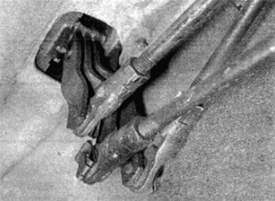
Pic. 3.14. Pry up the retainers and disconnect the gear selector links from the lever assembly
15. Make a fixing rod according to the dimensions shown in fig. 3.15. It is best to use a metal bar.
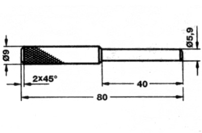
Pic. 3.15. Locking rod for shift linkage adjustment
All dimensions are in mm
16. Insert the locking rod through the holes provided in the selector levers (see fig. 3.16).
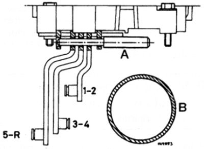
Pic. 3.16. Locking rod installed in the gear selector levers
A Fixing rod
To cardan shaft
17. With the gear levers fixed, it becomes possible to easily move the gear shift rods onto the lever pins. If necessary, adjust the position of the shift rod ends so that the rods can be pushed onto the lever pins as follows:
- A) Loosen the shift rod end.
- b) Rotate the tip to set the desired length of the rod.
- V) Tighten locknut.
18. When the adjustment is completed, install the latches to secure the shift lever rods to the lever pins, then remove the fixing rod.
19. Lower the vehicle to the ground and check the operation of the gearshift mechanism. Take a test drive and make sure all gears can be easily engaged.