



For automatic clearance adjustment, an adjustment lever with a tension spring is installed near the parking brake lever, with the help of which the plunger of the adjustment mechanism can be extended. Brake linings belong to the category of materials that require an operating permit and are included in the General Operating Permit Register (ABE).
In addition, they are selected by the manufacturer for specific vehicle models. Therefore, it is recommended to use only pads offered by the manufacturer or approved by the Federal Automobile Administration. Such pads have a number assigned to them by the Federal Automobile Administration.
Attention! If the brake pads are to be reinstalled for further use, they must be marked before removal. It is not allowed to switch the pads from the right wheel to the left and vice versa. Such a switch may result in uneven braking of the wheels. Only original brake pads or pads recommended by the vehicle manufacturer must be installed. Be sure to change all the brake pads on the front wheels, even if only one of them has reached the wear limit.
Attention! It is recommended to remove the brake mechanism only on one side so that, if necessary, you can check on the other side.
Removal
Attention! Before disassembling individual elements of the drum brake mechanism, remember or mark their installation position. If necessary, check against the mechanism on the other side.
1. Mark the position of the rear wheels on the hubs with paint. This will allow you to install the balanced wheel in its original position during assembly.
2. Loosen the wheel mounting bolts. The car must stand on its wheels when performing this operation.
3. Place the car on jack stands, unscrew the wheel bolts and remove the rear wheels.
Warning! Jacking up a vehicle or placing it on jack stands is dangerous. Therefore, it is recommended that you familiarize yourself with the safety precautions set out in Chapter "Jacking up a car".
4. Release the parking brake.
5. Unscrew the mounting bolt 1 and remove the brake drum 2 from the hub (see illustration).
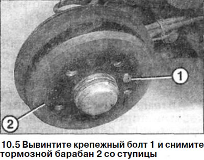
Caution! A tightly seated brake drum can be knocked off the hub with light blows from a plastic hammer and then removed by carefully pressing with a screwdriver.
If the brake drum does not give in and cannot be removed from the hub, then you should proceed as follows:
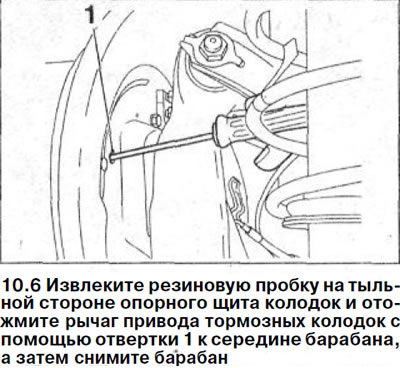
6. Remove the rubber plug on the back of the brake shoe backing plate and push the brake shoe actuator lever with screwdriver 1 towards the middle of the drum, then remove the drum (see illustration).
7. Disconnect the return spring 1 using the HAZET 797 pliers (see illustration).
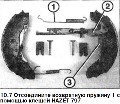
8. Disconnect the expansion bar 2 from the brake shoe lever and disconnect the tension spring 3 from it (see illustration 10.7).
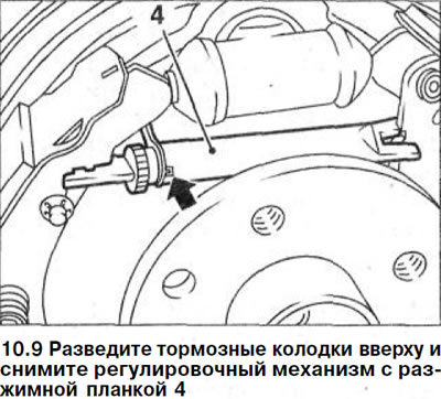
9. Spread the brake shoes at the top and remove the adjusting mechanism with the expansion bar 4 (see illustration).
10. Press screwdriver 2 on clamp 1 of the pin head that secures the brake shoe and remove it from the pin (see illustration).
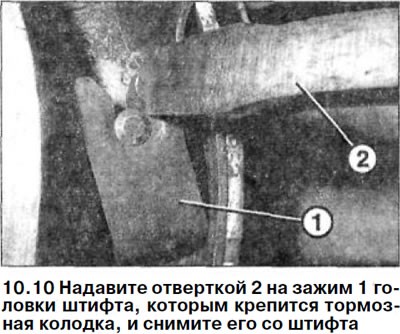
At the same time, support the pin with your hand on the other side. After releasing the pin head, remove the clamp from it and remove the pin. To make this work easier, you can use the HAZET 2796-1 spring removal pliers.
Text republished from the website: MERCEDESMAN.ru
11. Remove the pin on the second shoe in the same way.
12. Disconnect the lower brake shoe tension spring.
13. Remove the brake pads by disconnecting the handbrake cable from the rear pad.
14. Wrap the brake cylinder at the ends with a fastening belt or install clamps so that the piston does not rise above the brake cylinder. When removing the pads, do not pull out the piston, because otherwise air will get into the brake system and it will have to be bled later.
Caution! Do not damage the wheel brake cylinder seals.
Caution! When the brake pads are removed, do not press the brake pedal. Otherwise, the piston will be pushed out of the brake cylinder. If the piston does come out of the cylinder, remove the caliper and deliver it to a specialized workshop for repair.
Examination
Be sure to replace all four brake pads with new ones. The installed pads must be from the same manufacturer. Using a vacuum cleaner, clean the brake drum and caliper from dust and wipe them with alcohol.
Warning! Brake dust can be harmful to health. Use a respirator to avoid dust getting into the respiratory tract. When the brake pads are removed, do not press the brake pedal. Otherwise, the piston will be squeezed out of the brake cylinder.
15. Move away with your hand or pry with a blunt object the dust boots 1 and 2 of the wheel brake cylinder (see illustration).
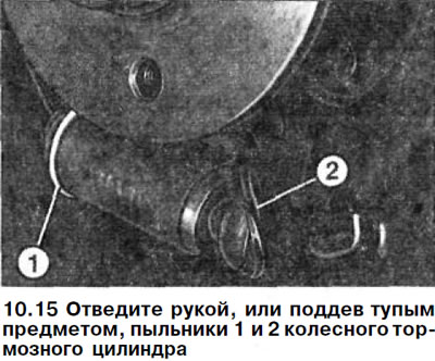
Attention! Do not pull the piston out of the brake cylinder.
If it is dry under the boot, then install it in its original place. If brake fluid flows out of the cylinder, then the wheel brake cylinder must be replaced.
16. Replace damaged anthers.
17. Check the surface of the brake drum by touch for grooves and corrugations. Damaged drums must be replaced or ground down. Measure the inner diameter of the drums. The wear of both drums should be the same. When the wear limit is reached, both rear brake drums should be replaced with new ones. For specifications and wear parameters, see the "Specifications" section.
18. Sand with sandpaper (grain size 150) minor irregularities and traces of rust on the surface of the drums.
Installation
19. Clean the surface of the brake pad backing plate and lubricate it with a thin layer of high-temperature paste before installation, such as, "LUBRITHERM G 2000".
Caution! The paste should never come into contact with the friction surfaces of the brake pads or brake disc. If it does come into contact with the paste, remove it immediately and wipe the surfaces with alcohol if necessary.
20. Lubricate the threads and contact surfaces of the adjusting gear axle, as well as the axle of the lever to which the expansion bar is attached, with a thin layer of protective paste.
21. Completely unscrew the adjusting gear shaft 1 from the expansion bar 2 and check the thread for ease of movement of the shaft. Make sure that the bimetallic washer 3 is accurately seated in the groove 4 of the expansion bar (see illustration).
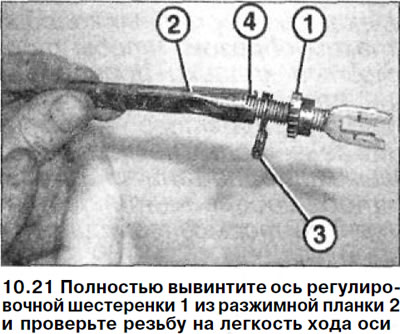
22. Secure the handbrake cable to the rear shoe and ensure that it is installed correctly.
23. Secure the lever 1 of the expansion bar to the lower pin of the front brake shoe (see illustration).
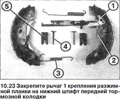
24. Fasten the tension spring 2 to the release bar lever and to the brake shoe (see illustration 10.23).
25. Fasten the lower tension spring 3 to both pads (see illustration 10.23). In this case, one spring hook is inserted from the rear side through the hole on the rear brake shoe clamp.
26. Install the brake shoes onto the backing plate and ensure they are seated correctly on the lower guide.
27. Secure the brake shoes to the backing plate by inserting the retaining pins 4 into the holes on the backing plate from the rear side and inserting their holes onto the brake shoes. Push the clamps 5 onto the retaining pins of the shoes from below using a screwdriver so that they go under the heads of the pins. In this case, the pins should be supported and pressed by hand on the rear side of the brake shoe backing plate (see illustration 10.23).
28. Remove the belt or spring from the wheel cylinder that was installed to prevent the piston from coming out.
29. Move the brake shoes apart at the top and install the expansion bar between them, securing the axle of the adjusting gear on the front shoe. In this case, the flat side of the bimetallic washer faces the brake shoe support shield, and the protrusion on it (see arrow in illustration 10.9) entered the groove on the expansion bar.
Caution! If necessary, compare the setting of the adjusting mechanism with the position of the adjusting mechanism on the other wheel.
30. Secure the upper tension spring first to the rear brake shoe, then hook the extended spring hook with special pliers or suitable needle-nose pliers to the front shoe.
Caution: Compare this setting with the position on the other wheel.
Caution: Before installing the brake drum, check the correct installation of the brake shoes, springs and adjusting mechanism by comparing with another wheel.
31. Install the brake drum on the hub so that the holes for the mounting bolts coincide with the holes on the cross member flange.
32. Secure the brake drum with new self-locking bolts and tighten them to 10 Nm.
33. Lubricate the flange of the rear wheel hub with a thin layer of plastic grease.
34. Adjust the parking brake, see the relevant chapter.
Caution! For vehicles with drum brakes, adjust the brake shoe adjuster so that the brake shoes are fully seated on the brake drum. To do this, start the engine and depress the brake pedal several times to ensure sufficient braking force.
35. Install the wheels in accordance with the marks made during removal. Before doing this, lubricate the centering seat of the wheel disk on the hub with a thin layer of grease. Do not lubricate the wheel mounting bolts. Replace rusted bolts with new ones.
36. Screw in the wheel mounting bolts and lower the car onto the wheels.
37. Tighten the bolts in a cross pattern to 110 Nm.
38. Carefully break in the new brake pads. To do this, brake several times, bringing the speed from about 80 km/h to 40 km/h and pressing the brake pedal lightly. Let the brakes cool down in between. During the first 200 km of driving with new brake pads, avoid unnecessary braking until the car has come to a complete stop.
Attention! Brake linings must not be thrown away with regular garbage, as the dust that forms on them is hazardous to health. They must be disposed of only at special points.
Attention! Make sure that:
- a) the brake hoses are securely connected;
- b) brake hoses are secured in holders;
- c) the brake drive bleed nipples are screwed in;
- d) there is a sufficient volume of brake fluid in the expansion tank.
39. Perform a leak test of the brake system by starting the engine. Press the brake pedal with a force of 200-300 N (20-30 kg) and hold it for about 10 seconds. The pressure in the system and, accordingly, the resistance of the brake pedal, should not decrease. Check all connections for leaks.