
The brake system is divided into two circuits, functioning diagonally. One hydraulic circuit acts on the front right and left rear wheels, and the other - on the front left and rear right.
This ensures that the vehicle stops with sufficient efficiency in the event of a failure of one of the circuits, for example, in the event of a leak in one of the circuits of the service brake system.
The pressure for both circuits is created by double (tandem) master brake cylinder when applied to the brake pedal (see illustration 1.0).
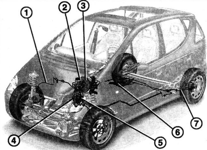
1.0 Brake system of A-class cars
1 - brake pipeline
2 - brake fluid expansion tank
3 - vacuum brake booster
4 - ABS hydraulic block
5 - ABS control unit
6 - parking brake lever
7 - cable pull of the parking brake
The brake fluid expansion tank is located in the engine compartment above the brake master cylinder behind the washer fluid reservoir. The entire brake system is supplied with brake fluid from it.
The amount of brake fluid in the expansion tank must be checked regularly.
The vacuum brake booster uses the vacuum in the intake manifold of the gasoline engine and, when the brake pedal is depressed, increases the applied force.
Due to the fact that the diesel engine has almost no vacuum on the intake manifold, vehicles with a diesel engine are equipped with a special vacuum pump for the brake booster.
The vacuum pump is mounted on the right side of the engine block and is driven by the camshaft.
A-class cars are equipped with disc brakes in front and drum brakes in the rear.
Cars with engine power over 90 hp, as well as cars with an extended body base, also have disc brakes on the rear axle.
These disc brakes have a floating caliper with a single piston, which is enough to press both brake pads against the brake disc. The parking brake acts through a cable drive on the brake mechanisms of the rear wheels.
The brake pads on the rear wheels are self-adjusting, so adjusting the parking brake is only necessary in rare cases, such as after a repair.
Vehicles with disc brakes are additionally equipped with two brake drums for the parking brake pads, which are integral with the brake discs.
Attention! Work on the brake system requires meticulous cleanliness and precision. If the necessary experience is not available, it is better to entrust such work to a specialized workshop.
Attention! When driving on wet roads, the brakes must be applied from time to time to clean the brake discs. Although under the action of i centrifugal forces water is discharged from the brake discs, they still remain a thin layer of rubber wear products, grease and other contaminants that impair the response of the brakes.
Burnt dirt on the brake linings and clogged water drainage grooves in the linings lead to serrated brake discs. Because of this, the effect of the brakes may deteriorate.
Attention! When cleaning the brake system, dust is generated. This dust is harmful to human health. Therefore, when cleaning the brake system, use a respirator to prevent brake dust from entering the respiratory tract.
Anti-lock braking system (ABS)
The anti-lock braking system prevents the wheels from locking during heavy braking. Thanks to this, the car remains steerable even with full braking.
The ABS control unit receives a signal from the sensors installed on all four wheels about the number of wheel revolutions. As soon as one of the wheels is on the verge of blocking, this is registered by the corresponding sensor and reported to the ABS control unit.
In response, the brake pressure in the respective brake caliper is reduced and thus the wheel is not blocked.
This process is repeated under heavy braking until the car comes to a complete stop for each wheel separately until the brake pedal is released or almost until the car stops.
Anti-slip system (ASR)
Electronically controlled traction control (or torque control system) when starting off, it brakes the slipping wheels and transfers the torque to those wheels that are firmly attached to the surface.
The system monitors the rotation of the wheels and slows down, increasing the pressure in the brake mechanism of the wheel that begins to slip.
Thus, the traction force is used to the maximum extent by the wheels having good grip on the ground or road surface.
In extreme cases, if three wheels are slipping, then the force is transferred to the only non-spinning one. As soon as one of the wheels is on the verge of slipping, the orange ASR warning light with a triangle symbol starts flashing on the instrument panel.
The traction control system can perform engine braking if necessary. In this case, the electronic accelerator control unit activates the executive motor, which covers the throttle valve.
This happens when, when one of the wheels slips, it automatically brakes, and the second rear wheel at that moment approaches the limit of slipping.
The electronic traction control control unit recognizes that the engine tractive effort is too high at this point.
Within milliseconds, the system's electronic control unit changes the position of the throttle valve to limit the supply of fuel to the engine. This happens even when the driver fully depresses the accelerator in extreme cases.
With a decrease in fuel supply, engine traction is reduced and both rear wheels can rotate normally. If at this moment the engine is cold, then the ignition timing is additionally adjusted.
Traction control can be turned off using the switch located on the center console. In this case, the ASR warning light on the instrument panel lights up.
Attention! When driving on sand, gravel or deep snow, it may be necessary to drive with wheel spin and without engine braking. In such cases, ASR can be deactivated by pressing the switch on the center console. However, the system will still monitor the rear wheel spin when the vehicle is moving at medium speed.
Automatic stability control system (ESP)
A-class cars are equipped as standard with an automatic stability control system (ESP), which is based on the capabilities of the ABS and ASR systems and complements them, reducing the risk of skidding the car, even in cases where the accelerator pedal is not pressed or braking is not performed.
When cornering at high speeds or when making sharp manoeuvres, the stability control recognizes «intention» vehicle to lose stability.
To this end, the ESP control unit takes into account the information from the sensors about the angle of rotation, and also, based on the speed of the vehicle, calculates the angular velocity (rotational speed) vehicle relative to the vertical axis and instantly determines the moment when the vehicle may lose stability.
By adjusting the pressure in the brake mechanisms of the respective wheels, as well as slowing down the engine, ESP ensures that the car instantly returns to a position in which nothing threatens its stability.
If, for example, the vehicle's front wheels are in danger of skidding while driving in a tight bend, the system deliberately brakes the rear wheel on the inside of the curve and thereby stabilizes the vehicle. If there is a threat of skidding of the rear wheels, then the front wheel moving along the outer turning line is braked.
ESP operation is indicated by the warning light on the instrument panel. The driver in such cases must take into account the traffic situation and change the speed.
Brake booster (BAS)
MERCEDES-BENZ A-class cars are equipped as standard with a brake booster.
The need to install such an amplifier is due to the fact that most drivers in a critical situation brake too late or with less effort than necessary, which increases the stopping distance. By how hard the brake pedal is applied, BAS determines that a hazardous situation has occurred.
Within milliseconds, it creates the necessary pressure in the brake system and reduces the braking distance at a vehicle speed of 100 km / h by 45% compared to the braking distance of a car without booster.
The BAS/ESP warning light comes on when the ignition is switched on and goes out when the engine is started.
Notes related to the ABS/ASR/ESP/BAS systems
A safety switch in the electronic control unit ensures automatic shutdown of the system in the event of a defect (e.g. broken wire) or in the event of a voltage drop in the on-board network (when the battery voltage is less than 10.5 V).
This condition is indicated by the orange ABS warning light on the instrument panel.
In this case, ASR, ESP and BAS are disabled, which is confirmed by the ESP warning light coming on. At the same time, the normal braking system continues to function and the car behaves like a car without ABS.
If the ESP warning light comes on and stays on while driving, this is an indication of a defect in the BAS or ESP system. They turn off, but the brake system remains normal.
Attention! If the brake warning light comes on while driving (red with an exclamation point), you should immediately stop and find out the cause. The main reasons for the light bulb to come on are a low level of brake fluid in the expansion tank or driving with the parking brake applied.
If the ABS warning light comes on while driving, do the following:
1. Stop, turn off and start the engine again.
2. Check battery voltage. If it is less than 10.5 volts, charge the battery.
Attention! If the ABS warning light comes on at the beginning of the movement and goes out after a while, then this indicates that the battery voltage was too low, but then increased while driving as a result of recharging from the alternator.
3. Check if the terminals are securely fastened to the battery poles.
4. Place the vehicle on jack stands and remove the wheels. Check wheel speed sensor wires for external damage (grinding).
Further checks of the ABS must be carried out in a workshop. The ABS control unit runs a self-diagnosis program and all faults are logged. These faults can be read in the workshop using a special tester, and then eliminated.
Attention! When working with electric welding, the plug of the ABS electronic control unit must be disconnected. The plug is located in the engine compartment on the passenger side under a removable cover; disconnect the plug only when the ignition is switched off. When performing paintwork, the control unit can be subjected to short-term exposure to high temperatures not exceeding +90°C.