



Contents: Removal ↡ Installation ↡
This chapter describes the procedure for removing and installing the front brake caliper. Removing the rear brake caliper is generally done in the same way. Features related to the front or rear brake mechanisms are highlighted.
Removal
1. Mark the position of the front wheels relative to the hub with paint. This will allow you to install the balanced wheel in its original position during assembly.
2. Loosen the wheel mounting bolts. The car must stand on its wheels when performing this operation.
3. Place the car on jack stands, unscrew the wheel bolts and remove the wheels.
Warning! Jacking up a vehicle can pose a risk of injury. Please read the following instructions before performing this work relevant chapter.
Attention! If the caliper is removed only to dismantle the brake pads or brake disc, then the brake hose does not need to be disconnected from the caliper. In this case, secure the caliper with the hose connected to the body with wire so that the brake hose does not twist or stretch.
4. Disconnect the brake hose from the caliper, see the relevant chapter.
Caution! When the brake circuit is opened, brake fluid will leak out. Collect the fluid in a container intended for brake fluid. Brake fluid can be removed from the expansion tank using a siphon before removing the caliper.
5. Remove the brake pads, see the relevant chapter.
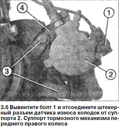
6. Front right wheel brake caliper. Unscrew bolt 1 and disconnect the pad wear sensor plug from the caliper 2 (see illustration).
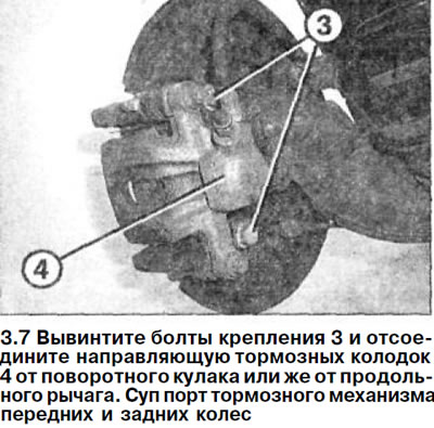
7. Front and rear brake caliper. Unscrew the mounting bolts 3 and disconnect the brake shoe guide 4 from the steering knuckle or from the trailing arm, respectively (see illustration).
(Full article available on the resource: MercedesMAN.ru)
Caution! The brake shoe guide bolts are tightened with a high tightening torque. Make sure the car is firmly on the jack stands. These bolts can be loosened before placing the car on the jack stands. When unscrewing the bolts, the spanner should be placed horizontally.
Attention! If the caliper is not to be replaced, take measures to ensure that the brake cylinder piston is not inadvertently pressed out.
Installation
8. Install the brake shoe guide 4 in place and secure it with two new self-locking bolts 3, respectively, on the steering knuckle or on the trailing arm. The tightening torque of the brake shoe guide pins for the front wheels is 115 Nm, and for the rear wheels - 55 Nm.
Caution! High tightening torque. Make sure the car is firmly supported on jack stands. Mount the torque wrench horizontally. The final tightening of the bolts can also be done after the car has been installed on the wheels.
9. Right wheel brake caliper. Secure the brake pad wear sensor to the brake pad guide with a new self-locking bolt and connect the plug.
10. Install the brake pads, see the relevant chapter.
Caution! There must be no grease or oil on the surfaces of the brake disc and brake pads.
11. Connect the brake hose to the caliper, see the relevant chapter.
Caution! The hose must not be twisted.
12. Remove air from the brake system, see the relevant chapter.
13. Install the wheels in accordance with the marks made during removal. Before doing this, lubricate the centering seat of the wheel disk on the hub with a thin layer of grease. Do not lubricate the wheel mounting bolts. Replace rusted bolts with new ones.
Caution: Make sure that the front wheel cylinder brake hose will not rub when the steering wheel is turned to its maximum angle.
14. Screw in the wheel mounting bolts and lower the vehicle.
15. Tighten the bolts in a cross pattern to 110 Nm.
Attention! Press the brake pedal several times until you feel a strong resistance to pressing the vehicle while it is parked on its wheels. When you do this, the brake pads are centered and they automatically adjust to the working position.
16. Check the brake fluid level in the expansion tank. If necessary, top up to the maximum mark.
Caution! New brake pads must be run in.
Attention! Make sure that:
- a) the brake hoses are securely connected;
- b) the brake hose is secured in the holder;
- c) the brake drive bleed nipples are screwed in;
- d) there is a sufficient volume of brake fluid in the expansion tank.
17. Perform a leak test of the brake system with the engine running.
To do this, press the brake pedal with a force of 200-300 N (20-30 kg) for about 10 seconds. The pressure in the system and, accordingly, on the brake pedal, should not drop. Check all connections for leaks.