
Features relating to the front or rear wheels are highlighted.
Brake linings belong to the category of materials for which an operating permit is required and they are included in the General Operational Permit Register (ABE).
In addition, they are selected by the manufacturer for certain car models. Therefore, it is recommended to use only pads offered by the manufacturer or approved by the Federal Automobile Administration. These pads have a number assigned to them by the Federal Automobile Administration.
Attention! If the brake pads are to be reinstalled for later use, they should be marked before removal. Swapping pads from the right wheel to the left and vice versa is not allowed. Such a rearrangement can lead to uneven braking of the wheels. It is obligatory to install only original brake pads or pads recommended by the vehicle manufacturer. Be sure to change all front brake pads, even if only one of them has reached the wear limit.
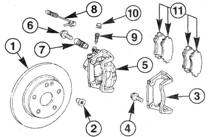
2.0 Front disc brake pads
1 - brake disc
2 - locking screw. Tightening torque 10 Nm. To be replaced after each disassembly
3 - shoe guide
4 - bolt. Tightening torque 115 Nm. To be replaced after each disassembly
5 - support
6 - caliper mounting bolt. Tightening torque 30 Nm
7 - sealing cuff
8 - brake lining wear sensor
9 - bleed valve
10 - dust cap of the bleed valve
11 - brake pads
Removing
1. Mark the position of the front wheels on the hub with paint. This will allow the assembly to set the balanced wheel in its original position.
2. Loosen the wheel bolts. The vehicle must be on wheels during this operation.
3. Install the front of the car on the goats and, having unscrewed the bolts, remove the front wheels.
Attention! There is a risk of injury when the vehicle is placed on jack stands. Therefore, you should first familiarize yourself with the safety measures when jacking up the car.
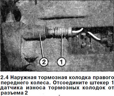
4. Outer brake pad of the right front wheel. Disconnect plug 1 of the brake pad wear sensor from connector 2. Do not pull on the wire, but on the plug housing (see illustration).
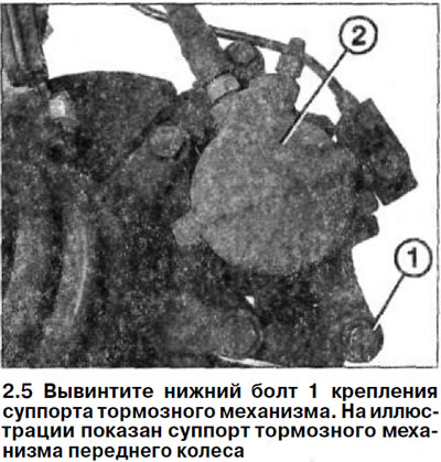
5. Unscrew the lower bolt 1 fastening the brake caliper (see illustration).
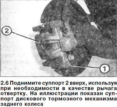
6. Lift support 2 up, using a screwdriver as a lever if necessary (see illustration).
7. Secure the caliper with wire to the steering knuckle or trailing arm.
8. Remove the brake pads 3 from the shoe guide (see illustration).
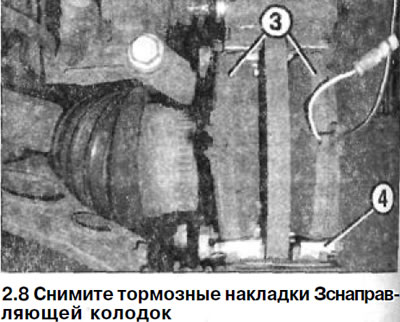
9. Pry off the upper and lower clamping springs of 4 pads with a screwdriver and remove them (see illustration 2.8).
Attention! With the brake pads removed, do not press the brake pedal. Otherwise, the piston will be squeezed out of the brake cylinder. If the piston is still out of the cylinder, then remove the caliper and deliver it to a specialized workshop for repair.
Examination
10. Clean the seating and guide surfaces of the brake pads, as well as the brake disc with a suitable soft metal brush and wipe it with a rag soaked in alcohol. Do not use solvents containing mineral oils or sharp-edged tools.
Attention! Use only alcohol to clean the brake mechanism.
11. Before installing the pads, check the brake disc for the absence of grooves by running your hand over it. Brake discs with a serrated surface can be repaired in a workshop if their remaining thickness allows it. Otherwise, replace the disks with new ones.
12. Measure the brake disc thickness. When the maximum permissible residual thickness is reached, replace the brake disc, see relevant chapter.
13. Check the condition of the retaining springs4 of the brake pads (see illustration 2.8) and replace them if necessary.
14. Check up a condition of a cuff of the piston of the brake cylinder. Replace a damaged and cracked cuff immediately, because dirt that has penetrated through a damaged cuff quickly leads to depressurization of the brake caliper. In this case, the brake caliper must be removed and disassembled (work is done in the workshop).
15. Make sure that the brake fluid does not come out from under the piston of the brake cylinder.
16. Check up a condition and landing of a cap of the piston of the brake cylinder. If necessary, take the caliper to a workshop for overhaul or replace it with a new one.
17. Check up also a condition of dustproof caps on heads of directing fingers of a support. If they are damaged, then replace them.
Attention! If the brake pads are badly worn, then it is necessary to check the ease of movement of the piston of the brake cylinder. To do this, insert a wooden block into the front caliper and ask an assistant to slowly press the brake pedal. The piston of the brake cylinder should move easily. To check, you must install a second caliper or use a caliper from another wheel. If the piston has a hard stroke, repair the caliper (work being done in the workshop).
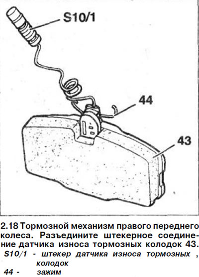
18. External brake pad of the right front wheel. Disconnect the plug connection of the brake pad wear sensor 43. If the sensor is damaged, replace it with a new one (see illustration).
Installation
19. Press the piston of the brake cylinder using a special pressing tool. You can get by with a wooden rod made of hardwood (hammer handle), but do not distort the piston and do not damage its surface and the dust cap itself (see illustration).
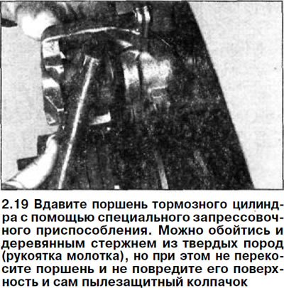
Attention! When the piston is depressed, the brake fluid is squeezed out of the wheel brake cylinder into the expansion tank. Keep an eye on the level of brake fluid in the expansion tank and remove it if necessary.
Attention! To withdraw brake fluid from the expansion tank, use a siphon or a plastic bottle that is not destroyed by brake fluid. Do not use regular drinking water bottles! Brake fluid is poisonous and must never be sucked out by mouth through a hose. Use a siphon. And after replacing the brake pads, the level of brake fluid in the reservoir should not exceed the maximum mark, because. when heated, it expands. Leaking brake fluid flows down the brake master cylinder, destroying the paintwork and causing corrosion.
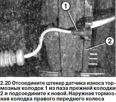
20. External brake pad of the right front wheel. Disconnect the plug of the brake pad wear sensor 1 from the groove of the old pad 2 and connect it to the new one (see illustration).
21. Install the upper and lower retaining springs into the shoe guides.
22. Install the brake shoes in the retaining springs on the rail. The pads are placed on the side, obliquely.
Attention! The surfaces of the brake disc and brake linings must be free of grease or oil.
23. Carefully reinstall the caliper, avoiding stress on the top guide bolt.
24 Fasten the caliper at the bottom with a new self-locking bolt 1 and tighten it to 30 Nm (see illustrations 2.5 and 2.6).
25. Tighten the lower caliper mounting bolt on the shoe guide with a force of 30 Nm.
26. External brake pad of the right wheel. Install the lining wear sensor in the plug connection. If the sensor wire is long, then wind it up so that it does not sag or fray.
27. Establish forward wheels according to the marks put at removal. Before doing this, lubricate the centering seat of the wheel disc on the hub with a thin layer of grease. Do not grease wheel bolts. Replace rusted bolts with new ones.
28. Screw in bolts of fastening of wheels and lower the car on wheels.
29. Tighten the bolts in a cross pattern to 110 Nm.
Attention! Squeeze out a few times a brake pedal against the stop, the strong resistance to pressing is not felt yet. When this action is performed, the brake pads are centered and they self-adjust to the working position.
30. Check up level of a brake liquid in a compensatory tank. If necessary, add fluid up to the maximum mark.
31. Carefully run in new brake pads. To do this, brake several times, bringing the speed from about 80 km / h to 40 km / h and lightly pressing the brake pedal. Let the brakes cool down in between. During the first 200 km of driving with new brake pads, avoid unnecessary braking until the car comes to a complete stop.
Attention! Brake linings must not be disposed of with normal waste, as the dust that forms on them is hazardous to health. They should be disposed of only at special points.
Attention! Make sure that:
- A) brake hoses are securely connected;
- b) brake hoses are fixed in holders;
- V) fittings for bleeding the brake actuator are wrapped;
- G) there is enough brake fluid in the expansion tank.
32. Perform a brake leak test by starting the engine.
To do this, depress the brake pedal with a force of 200-300 N (20-30 kg) and hold it for about 10 seconds. The pressure in the system and, accordingly, the resistance of the brake pedal, should not decrease. Check all connections for tightness.