
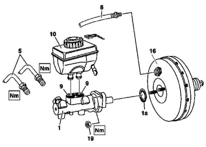
GTZ installation details (on the example of models with AT, version 1)
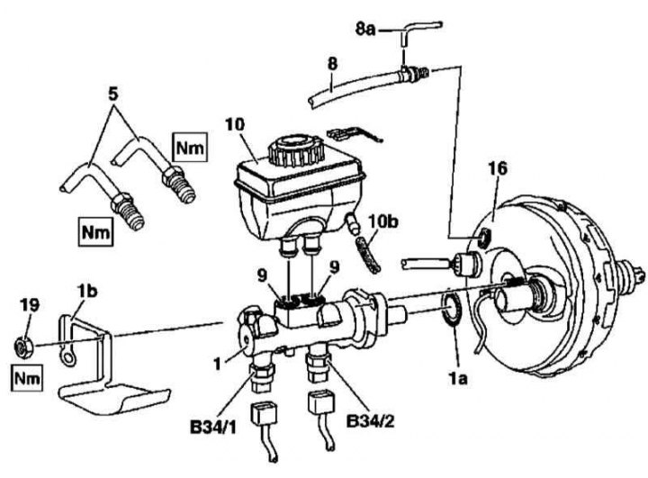
GTZ installation details (on the example of models with AT, version 2)
Removal / installation of the brake booster
Removal / installation of the brake booster
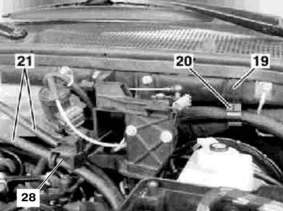
21 - Hoses
28 - Bracket
1. Illustrative material on the procedure for removing / installing the brake booster is presented in the illustrations, which include all references in the text, unless otherwise indicated.
2. Open the hood and lock it in an upright position.
3. Remove powertrain trim panels and fuse/relay mounting block covers.
4. Disconnect the electrical wiring from the GTZ tank (10).
5. Disconnect the vacuum line (8) from the brake booster (16).
6. On diesel models, release the vacuum line from the clamps on the bulkhead (8a), as well as an auxiliary line.
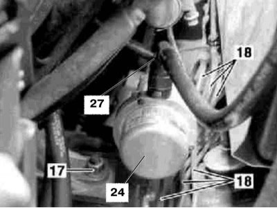
7. Disconnect from the vacuum pump (24) hose (27).
8. Release the hoses (21) from the bracket (28).
9. Separate the hoses from the fuse/relay mounting block and take them to the engine.
10. Having previously marked, disconnect the brake lines from the GTZ (5), - Seal the open ends of the male connectors immediately.
11. If equipped, disconnect the wiring from sensors 1 and 2 brake pressure ESP (B4/1 and B34/2), - release the locks on the undersides of the connectors.
12. Give self-locking nuts (19) GTZ mounts (1), - nuts must be replaced without fail.
13. If equipped, remove the heat shield (1b).
14. With the appropriate configuration, remove the anti-theft alarm siren from the bulkhead of the engine compartment.
15. Pulling strictly horizontally, remove the GTZ from the brake booster unit and transfer it to a workbench.
16. Check the cylinder for signs of developing leaks from the back of the primary piston, replace the assembly if necessary.
17. On models with manual transmission, disconnect the clutch operator hose from the GTZ reservoir (10b), - Seal the open end of the male connector immediately.
18. Pump out the tank (10) brake fluid, then, pulling vertically, remove it from the GTZ assembly (1).
19. Check the condition of the sealing sleeves (9), replace if necessary.
20. Installation is in reverse order - do not forget to replace the sealing ring (1a) and self-locking cylinder nuts.
21. Finally, bleed the brake system (see Section Bleeding the brake system).