
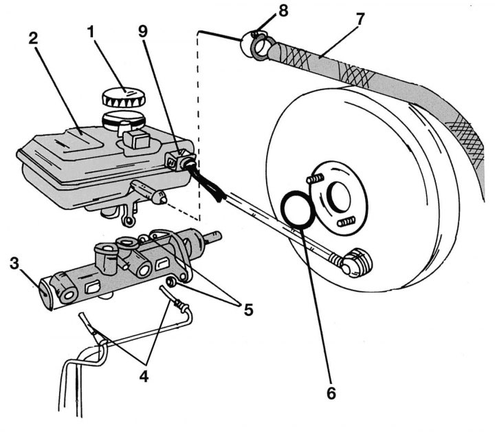
Pic. 290. Removal and installation of the main brake cylinder: 1 - stopper of the brake fluid reservoir; 2 - brake fluid reservoir; 3 — the main brake cylinder; 4 - union nut of the pipeline, 12–16 Nm; 5 - M8 fastening nut, 25–28 Nm; 6 - sealing ring (always replaceable); 7 - hydraulic hose; 8 - hose clamp; 9 - liquid level sensor plug
The main brake cylinder is installed in front of the vacuum booster housing and can be removed from the engine compartment. On fig. 290 shows the details of the master brake cylinder along with the booster. When removing the master brake cylinder, perform the following operations:
- unscrew the stopper of the brake fluid reservoir and remove the mesh under it by prying it with a screwdriver;
- disconnect the plug of the brake fluid level sensor from the side of the master brake cylinder;
- put one end of the hose on the bleeder valve of one of the front brake mechanisms, lower the other end into the prepared container. Unscrew the fitting and, pressing the brake pedal, pump out the fluid from the system. You can also pump out the fluid from the tank with a pear, as shown earlier. At the same time, put a rag under the cylinder so that drops of liquid do not fall on engine parts;
- clamp the hose leading to the brake fluid reservoir with a clamp;
- bite the hose clamp with side cutters and remove the hose from the tank;
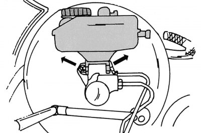
Pic. 291. Removing the brake fluid reservoir
- opening the tank mounts outwards (pic. 291), remove it;
- unscrew the pipes from the brake master cylinder and move them carefully to one side. Protect ends from dirt. Again, make sure that drops of brake fluid do not fall on the parts in the engine compartment. When assembling, tighten the union nuts of the pipelines with a torque of 12-16 Nm;
- unscrew the cylinder and remove it by tilting it away from the pressure rod. Make sure that the cylinder does not turn over and the rod does not come out of its seat. Remove the O-ring behind the cylinder.
Installation must be carried out in reverse order. The sealing ring is always replaced. Tighten the fastening bolts to 25 Nm. The booster rod does not require special installation in the cylinder. Finally, insert the reservoir, add brake fluid to the system and bleed as described below. Brake fluid volume for mod. 412D is 0.4 l, for other models - 0.3 l.