
Cross section of a standard type brake master cylinder
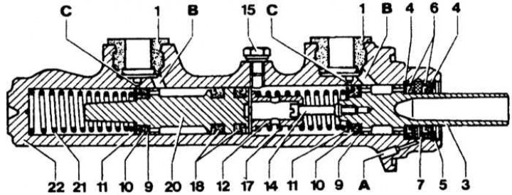
1 - sealing plug; 3 - piston (primary circuit); 4 - thrust washer; 5 - retaining ring; 6 - secondary and vacuum sleeve; 7 - intermediate ring; 9 - gasket washer; 10 - primary sleeve; 11 - support ring; 12 - spring holder; 14 - connecting screw; 15 - locking screw; 17— compression spring; 18 - separating sleeve; 20 - piston (secondary circuit); 21 - compression spring; 22 - body; A - a hole for removing leaks; B - filler hole; C - compensating hole
Cross section of brake master cylinder with differential pressure sensor
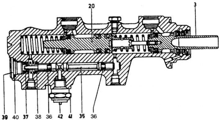
3 - piston (primary circuit); 20 - piston (secondary circuit); 35 - control piston; 36 - annular sleeve; 37 - spring; 38 - spring holder; 39 - screw; 40 - sealing ring; 41 - sensor; 42 - shutdown rod
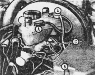
Electrical (A) and hydraulic (IN) brake master cylinder connections and fixing nut (WITH)
1. Prepare the workplace to prevent the ingress of brake fluid on paintwork surfaces.
2. Disconnect and plug immediately (sticky tape) hydraulic line from the brake master cylinder.
3. Disconnect the wire from the differential pressure sensor.
4. Disconnect the hydraulic hose from the clutch drive mechanism from the reservoir (for vehicles with manual transmission).
5. Turn away nuts and remove the main cylinder from an end face of the vacuum amplifier.
6. Remove the O-ring from the master cylinder flange groove.
7. Clean outer surfaces of master cylinder using denatured alcohol or brake cleaner.
8. Remove the brake fluid reservoir along with the sealing plug.
9. Drain the brake fluid reservoir into a clean container.
10. Slightly squeeze out the main piston and turn out a lock screw.
11. Take out a spring lock ring, take the piston, lock washers, an intermediate ring, auxiliary and vacuum couplings; to remove, light tapping on a wooden surface is allowed.
12. Remove the differential pressure sensor by unscrewing the end cap, lightly tapping to remove the control piston.
13. Turn away a cover of a tank of a brake liquid and remove the strainer.
14. Carry out cleaning of parts and their fault detection. Pay special attention to the surfaces of the pistons and cylinders, replace if necessary.
15. Install new seals on pistons by hand.
16. Lubricate the inner surfaces of the master cylinder and dip the main, auxiliary and control pistons in clean brake fluid.
17. Using the assembly mandrel, insert the details of the 1st and 2nd circuits into the cylinder. When carrying out the operation manually, pay special attention to the entry of seals, bending is not allowed.
18. Slightly press down on the main piston rod, insert and tighten the set screw with a new seal.
19. Insert the control piston in the same way, tighten the end cap with a new seal.
20. Clean the filter in a fresh (clean) brake fluid, insert it into the reservoir and screw on the filler plug.
21. Press the sealing plugs into the master cylinder and install the tank on it, first pushing it on one plug, then turning it 180°and pushing on the other plug.
22. Connect wire to differential pressure indicator and low fluid level indicator.
23. Connect the hoses and tighten the union nuts.
see also Vacuum brake booster.