
Warning: Brake fluid is poisonous: if fluid comes into contact with skin, wash it off immediately and thoroughly; If liquid enters the stomach or eyes, consult a doctor immediately. Some types of hydraulic fluid are flammable and may ignite on contact with hot parts; when servicing a hydraulic system, it is best to treat any fluid as flammable and take appropriate precautions as if it were gasoline. Brake fluid has a discoloring effect, especially on plastics, and should be washed off with plenty of clean water if spilled. In conclusion, it should be taken into account that the liquid is hygroscopic (it absorbs moisture from the air). The old fluid may be contaminated and unsuitable for further use. When adding or replacing fluid, always use the recommended type of fluid, and keep the fluid fresh and stored in a well stoppered container.
Removing
1. The main hydraulic cylinder is located in the cabin, mounted on the bracket of the clutch and brake pedals (see fig. 5.1). Hydraulic fluid for the assembly is supplied through a flexible rubber hose connected to the brake reservoir in the engine compartment.
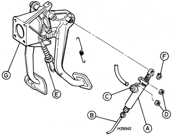
Pic. 5.1. Clutch master cylinder and pedal assembly
A. Master cylinder
B. Hydraulic tube fitting
C. Hydraulic hose fitting
D. Nuts
E. Clutch spring
F. Retaining ring
G. Pedal assembly
2. Disconnect the negative battery terminal.
3. Remove the driver's side instrument panel lower trim to gain access to the master cylinder and pedal assembly.
4. Pull back the butt mat and cover the floor under the pedal to protect it from spilled liquid.
5. To reduce fluid loss, use a clean syringe to remove fluid from the appropriate chamber of the brake system reserve tank so that its level drops below the level of the intake tube of the clutch master cylinder.
6. Place a suitable container under the master cylinder to catch spilled fluid.
7. Loosen the hydraulic tube fitting on the master cylinder and carefully pull the tube out. Plug the open ends of the tube and cylinder to keep them free from contamination and reduce fluid loss.
8. Remove the two nuts securing the cylinder to the pedal bracket.
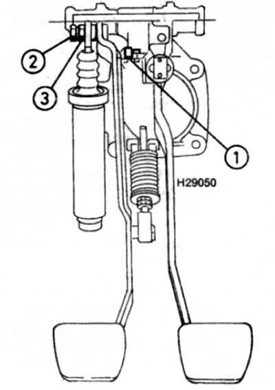
9. Pull the pedal up and remove the clutch spring thrust washer, spring and washer from the pusher (see fig. 5.9).
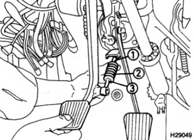
Pic. 5.9. Pull the pedal up and remove the thrust washer of the clutch spring from the pusher (1), spring (2) and puck (3)
10. Using a screwdriver or suitable pliers, remove the circlip securing the end of the master cylinder pusher to the pedals.
11. Disconnect the hydraulic pipes from the master cylinder (prepare for the fact that some of the liquid may spill), then pull the assembly out of the driver's footwell.
Disassembly
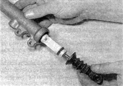
12. Remove the dust cover on the pusher from the cylinder body to gain access to the retaining ring (see fig. 5.12).
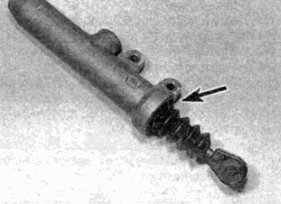
Pic. 5.12. Remove the dust cover (shown by arrow)
13. Using pliers for locking gauges, remove the locking ring, then remove the fastening washer (see fig. 5.13, a, b).
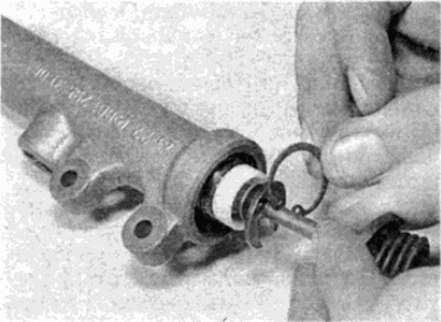
Pic. 5.13, a. Remove retaining ring...
Pic. 5.13b....and mounting washer
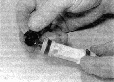
14. Remove the pusher and piston from the cylinder, followed by the piston spring (see fig. 5.14, a, b).
Pic. 5.14 a. Remove pushrod and piston...
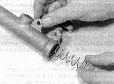
Pic. 5.14b....then the piston spring
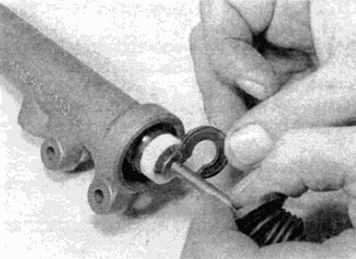
15. Remove the end cap and check valve at the end of the piston (see fig. 5.15).
Pic. 5.15. Remove end cap and piston check valve
16. Flush all parts in clean hydraulic fluid, then position for inspection.
17. Check up an internal surface of the cylinder and the piston. If scoring or sagging is found, replace the cylinder assembly. If the condition of the cylinder is normal, a repair kit consisting of new rubber seals should be purchased. Never use old seals.
18. Remove the old seal from the piston and install a new one using only your fingers. To facilitate installation of the gasket, lubricate it with clean hydraulic fluid. Make sure the sealing lip faces towards the piston spring.
19. Grease an internal surface of the cylinder and insert a spring.
20. Position the check valve and end cap on the piston and carefully insert the piston into the cylinder bore.
21. Install the fastening washers on top of the pusher, followed by the retaining ring.
22. Slightly push the piston down the cylinder bore and insert the circlip into the groove. Make sure the retaining ring is securely seated.
23. Replace the dust cover and position its end over the end of the cylinder.
Installation
24. Installation is carried out in the reverse order, taking into account the following points.
- A) Start assembly by installing the washer, clutch spring and spring thrust washer on the master cylinder pusher. Insert into the guide on the pedal bracket by depressing the clutch pedal.
- b) Make sure that the master cylinder pusher ear is installed with the flange facing the pedal.
- V) Do not install driver's side lower trim until you have checked pushrod adjustment (see par. 25).
- G) When finished, bleed the clutch hydraulic system as described in paragraph 6, then check the pushrod adjustment as described in the following paragraphs.
Pusher adjustment
Note: A bleed kit is required for this operation (see paragraph 6). Pumping is performed by two people.
25. To access the clutch slave cylinder, apply the parking brake, then jack up the front of the vehicle and place it on supports (see "Vehicle lifting and jacking up"). Using a clean syringe, draw approximately half of the fluid from the appropriate chamber of the brake reservoir.
26. Insert some metal strips (approximately 60.0x20.0x1.0 mm) between upper clutch pedal stop and rubber buffer (see fig. 5.26).
Pic. 5.26. Clutch Master Cylinder Pusher Adjustment
1 metal strips
2 Tension screw
3 Adjustment screw
27. Remove the dust cap and remove any dirt around the slave cylinder air release valve.
28. Attach a wrench and tube to the air release valve. Connect free end of tubing to bleeder (see paragraph 6).
29. Using a wrench, unscrew the air release valve.
30. Working in the driver's footwell, loosen the pinch screw on the pusher eccentric adjusting screw on top of the clutch pedal.
31. Ask an assistant to observe the fluid level in the tank.
32. Slowly turn the eccentric adjusting screw until the fluid level in the reservoir rises, then slowly turn the screw back until the fluid level stops rising.
33. Lock the adjusting screw by tightening the pinch screw.
34. Remove the metal strips from the pedal stop. The fluid level in the reservoir should rise.
35. Tighten the air release valve and disconnect the hose and bleeder. Install the valve dust cap.
36. Drink the liquid in the tank (see "Weekly check").
37. Check clutch operation with engine running.
38. Upon completion, install the lower decorative overlay of the front panel on the driver's side.