
Removing
1. Disconnect the negative battery terminal.
2. Remove the driver's side instrument panel lower trim to gain access to the master cylinder and pedal assembly.
3. Pull the floor mat back and cover the floor under the pedal to protect it from spilled liquid.
4. To reduce fluid loss, use a clean syringe to remove fluid from the appropriate chamber of the brake system reserve tank so that the level drops below the level of the intake tube of the clutch master cylinder.
5. Place a suitable container under the master cylinder to catch spilled fluid.
6. Loosen the hydraulic tube fitting on the master cylinder and carefully pull the tube out. Plug the open ends of the tube and cylinder to keep them free from contamination and reduce fluid loss.
7. Carefully unhook the brake pedal return spring (see fig. 7.7).
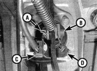
Pic. 7.7. Details of fastening of a pedal of a brake
A Hinge bolt retainer
B Hinge Bolt
With brake light cable plug
D Bracket for return spring
8. Disconnect the wire plug from the brake light switch, then unsnap the switch from the bracket on the pedal assembly.
9. Remove the retainer from the pedal pusher pivot bolt on the servo booster, then remove the pivot bolt.
10. Remove the four nuts securing the pedal assembly to the front of the bulkhead (note that these nuts also secure the vacuum brake booster), and a single bolt securing the assembly to the top of the bulkhead (see fig. 7.10, a, b).
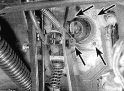
Pic. 7.10, a. Pedal Assembly Nuts (shown by arrows)...
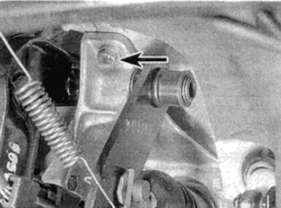
Pic. 7.10, b....and mounting bolt (shown by arrow)
11. Pull the pedal assembly back from the bulkhead to release the assembly from the studs, then lower the assembly, disconnect the hydraulic hose from the master cylinder (get ready for the liquid to flow out).
12. Remove the assembly from under the instrument panel.
13. Disassembly of the assembly is clear from Figure 7.13. Remember the location of all the parts in order to correctly assemble the assembly.
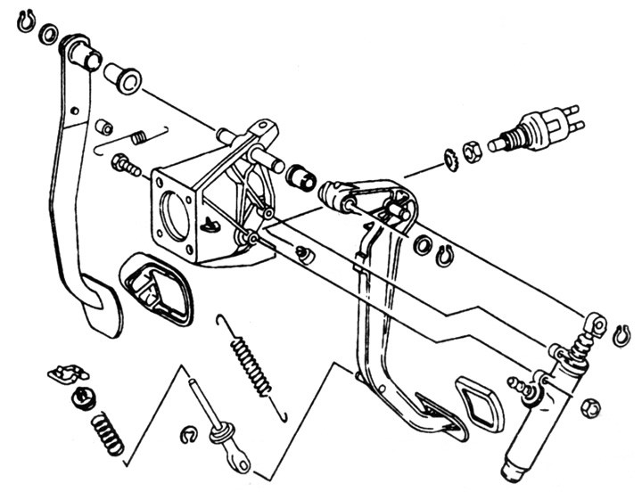
Pic. 7.13. Exploded view of the clutch and brake pedal assembly
Installation
14. Installation is carried out in the reverse order, taking into account the following points:
- A) Check the brake light switch adjustment as described in Chapter 9.
- b) When finished, bleed the hydraulic clutch system as described in paragraph 6.