
Clutch Assembly Component Installation Details
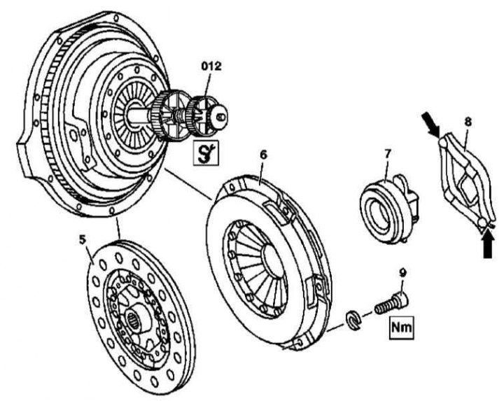
1. Illustrative material on the procedures for removing / installing clutch components is shown in the illustration, which includes all references in the text.
2. Remove manual transmission (see chapter Manual gearbox).
3. In several steps, no more than 1 ÷ 1.5 turns per approach, unscrew the fixing bolts (9) (Allen) and remove the clutch basket assembly (6) and driven disk (5), - when using a centering mandrel (012) act strictly in accordance with the instructions of the manufacturers of the device.
4. Assess the condition of the driven and pressure disks.
5. Assess the condition of the flywheel.
6. Replace defective components.
7. On models equipped with manual transmission series 717.4, remove the release bearing (7) and fork clutch release lever (8). Assess the degree of wear of the components, replace if necessary.
8. On models equipped with a 716.6 manual transmission, inspect the central operator for signs of wear and leaks. Replace if necessary.
9. Installation is carried out in the reverse order - make sure that the driven disk is installed correctly, on models with a manual transmission of the 717.4 series, lubricate the recesses in the forked clutch release lever under the spherical bolt of the box housing and the pusher rod of the slave cylinder (arrows).