
| Type and designation of manual transmission | |
| Models 163.136 | (ML 230) 6-speed, 716.644 (SG-S370/6.1) |
| Models 163.113 | (ML 270 CDI) 5-speed, 717.461 (GL_7b/29_B_5) |
| Type and volume of gear oil | See Specifications for Chapter Ongoing care and maintenance |
| gear ratios | |
RKPP 716.644 | |
| 5.01 |
| 2.83 |
| 1.78 |
| 1.25 |
| 1.00 |
| 0.82 |
| 4.56 |
| Data not provided |
| Tightening force of threaded connections, Nm | |
| RKPP 716.644 | |
| Bolts for fastening the gearbox to the engine | 40 |
| Drain plug of the manual transmission oil pan | 60 |
| Filler plug | 50 |
| Nuts / bolts of fastening of a back cross beam of the power unit to a body | 40 |
| Nut / bolt of fastening of a back pillow of a support of a suspension bracket of the power unit to transmission | 40 |
| Self-locking bolts securing the front camshaft to the transfer box output shaft | 40 |
| RKPP 717.461 | |
| Threaded pin of shift rod | 12 |
| Bolts for fastening the gearbox to the engine | |
| Bolts of fastening of transmission to the engine | |
M10x40 | |
| 55 |
| 40 |
| М10x90 | |
| 45 |
| 40 |
| Bolts for fastening the adapter casing to the gearbox crankcase | 20 |
Due to the energy released during combustion in the cylinders of the air-fuel mixture, the engine crankshaft develops torque, while its rotation frequency lies within a fairly narrow range. Most modern OHV engines develop their maximum torque at about 2500 rpm. When the engine speed is increased to 4500 rpm, its torque decreases so much that a further increase in power is no longer possible. Engines with an overhead camshaft (OHC) are able to develop significantly more torque, but in a much narrower speed range.
The use of such a component as a gearbox in the transmission line allows you to adjust the relationship between engine speed and the speed of rotation of the driving wheels of the car, ensuring a sufficiently high efficiency of the power unit output in almost any vehicle operating conditions.
Smooth transmission of torque from the crankshaft to the input shaft of the manual gearbox (RKPP) provides the clutch assembly, the design and principle of operation of which are discussed in the Chapter transmission line this guide. Sequential gear shifting in the process of changing the speed of the vehicle is provided through the use of a multi-stage gearbox in the gearbox. The gear ratios of each of the five / six steps of the manual transmission provide maximum efficiency in transferring the power developed by the engine to the driving wheels of the vehicle at various speeds.
On two of the Mercedes-Benz M-Class all-wheel drive models covered in this Guide, in addition to automatic transmissions (see chapter automatic transmission) manual transmissions can be used (RKPP) one of two types: 717.461 (ML 230) and 716.644 (ML 270 CDI). Both boxes are of the standard design used on most Mercedes vehicles with classic rear wheel drive (series 717.4 and 716.6).
The torque developed by the engine and converted in the manual transmission gearbox is removed from the rear end of the main shaft and transmitted to the input shaft of the transfer case, which further distributes it between the front and rear drive axles of the vehicle. Detailed information on the design and principle of operation of the transfer case is given in Chapter transmission line this guide.
Both gearboxes provide synchronization of all five (717.4) /six (716.6) gearshift steps for all forward gears.
It makes sense to pay a little attention to the features of the functioning of more modern six-speed manual transmissions.
Boxes of the 716.6 series belong to the class of fully synchronized 2-shaft 6-speed gearboxes with one reverse gear, which are widely used in both rear-wheel drive and all-wheel drive vehicles equipped with both gasoline and diesel engines.
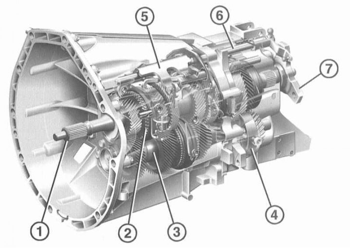
General view of manual transmission 716.6
1 - Gearbox input shaft; 2 - Synchronizing ring 5/6 gears; 3 - Shaft; 4 - Reverse bearing insert; 5 - Switching cam; 6 - Axis of inclusion; 7 - Flange of connection with cardan shaft
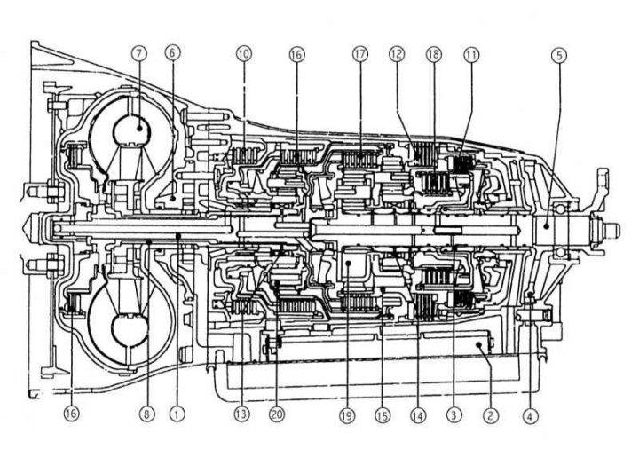
Manual transmission design 7.6.6
1 - Input shaft; 2 - Main shaft; 3 - Intermediate shaft; 4 - Front crankcase; 5 - Rear crankcase; 6 - clutch release device; 7 - Multi-cone switching synchronizer 1/2; 8 - Multi-cone switching synchronizer 3/4; 9 - Gear 1st gear; 10 - Gear 2nd gear; 11 - Gear 3rd gear; 12 - Gear 4th gear; 13 - Gear wheel of the 5th gear; 14 - Gear 6th gear; 15 - Reverse gear; 16 - Central switching rod; 17 - Internal switching module; 18 - Intermediate reverse gear
Proper use of the 6th gear allows you to achieve significant savings in fuel consumption by reducing the operating speed of the engine. Due to design features, 6-speed gearboxes have more weight than 5-speed ones.
The box receives torque from the engine through a conventional dry-type clutch equipped with an automatic wear compensator. The manual transmission case has a sealed design and is filled with gear oil that does not need to be replaced.
Accuracy and ease of switching with a short stroke is achieved by the following design features:
- The use of a rod-cable shifting drive with a central rod fixed in needle bearings;
- The use of multi-cone synchronizers for switching 1st, 2nd, 3rd and 4th gears;
- Full synchronous reverse gear.
Gear assemblies with shafts are placed between two bearing planes. The third bearing plane used in earlier 5-speed gearboxes has been eliminated in this design.
The two-section split crankcase is made of light alloy and sealed with a special liquid compound.
input shaft (1) fixed in the flywheel by means of a guide bearing, and in the transmission case by means of a deep groove ball bearing. Main (2) and input (1) the shafts are articulated with each other in the common plane of the transmission housing and are fixed by means of ball bearings with a deep groove (see ibid).
intermediate shaft (3) It has a lightweight hollow design and is mounted in a roller clutch and a deep groove ball bearing.
Due to the minimum manufacturing tolerances of half-crankcases and gears, as well as due to the use of roller couplings, the need for adjusting the axial play of the shafts is eliminated.
The movements of the gear lever are transmitted through the rods to the box. Removal of the manual transmission can be carried out separately from the engine, the need for removal arises when servicing the clutch, as well as if it is necessary to carry out a refurbishment / replacement of the manual transmission itself.
Due to the complexity of the design of the manual transmission, the lack of free sale of the necessary replaceable internal components and the need to use special equipment, the compilers of this Guide do not recommend car owners to overhaul the gearbox on their own. Repairing a box in a car service workshop is a rather expensive operation, which means that alternative options for replacing a failed unit with a new one or a refurbished one should be considered. Any useful information on the repair and replacement of the transmission can be obtained from Mercedes-Benz service stations. Regardless of the chosen troubleshooting method (repair or replacement), independent dismantling of the box from the car will significantly reduce material costs.
In this Part of the Chapter, the reader is offered descriptions of the processes for performing procedures that lie within the qualifications of an average amateur mechanic, such as general adjustment of the gearshift drive and removal / installation of the manual transmission assembly. Tips for managing shifting mi RKPP are set out in Chapter Controls and techniques for safe operation.
Information on automatic transmissions (AT) presented in Chapter automatic transmission.