



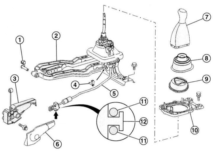
Design of the gear shift drive of the 716.644 series manual transmission (mL 270 CDI models)
1 - Mounting pin; 2 - Central unit of the switching drive; 3 - Bracket; 4 - Mounting pin; 5 - Drive cable; 6 - Bracket cover; 7 - Shift lever handle; 8 - Protective cover; 9 - Dust cover; 10 - Lid; 11 - Spring; 12 - Support
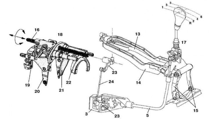
Design of the gear shift drive of the 716.644 series manual transmission (mL 270 CDI models)
3 - Bracket; 5 - Gear selection cable; 13 - Shift rod; 14 - Connecting lever; 15 - Articulated arms; 16 - Central shift rod; 17 - Base of the lever assembly; 18 - Internal switching module; 19 - 5/6 gear shift lever; 20 - 3/4 gear shift lever; 21 - 1/2 gear shift fork; 22 - Reverse gear engagement fork; 23 - Transmission levers; 24 - Gear selection rod
1. The design of the rod-cable shift drive for the 716.644 manual transmission is shown in the illustrations, the last of which includes all references in the text.
2. The lever assembly is no longer bolted to the floor of the passenger compartment, but is attached to the transmission.
3. This design is characterized by increased precision and ease of switching, as well as the absence of the need to organize a tunnel for laying moving components.
4. The articulated lever assembly, combined with the equipped rubber support cushions, ensures freedom of movement of the transmission-engine articulation.
5. Rotation of the central rod (16) around its axis is ensured by transverse displacements of the shift lever due to the organization of a cable drive.
6. The axial displacement of the central rod (16) is achieved by feeding the lever in the longitudinal direction using the switching rod (13).
Publication reprinted from this resource MercedesMan
7. To release the reverse gear lock, pull the shift lever handle upwards.