
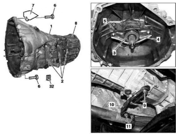
Details of the manual transmission installation 717.461 (models ML 230)
1 - Carter manual transmission; 2 - Executive switching levers; 3 - Release bearing; 4 - Forked clutch release lever; 5 - Resistant finger; 6 - Screw; 7 - Holder; 8 - Adapter case; 9 - Screw; 10 - Support bracket for suspension of the exhaust system; 11 - Nut; 32 - Retainer
1. Installation details of RKPP 717.461 on ML 230 models are shown in the illustration, which includes all references in the text.
2. Disconnect the negative cable from the battery.
3. Remove the transfer case (see chapter transmission line).
4. Give nuts (11).
5. Turn out bolts (9) and remove the exhaust system support bracket (10).
6. Remove the retainer (32) and disconnect the shift rod from the actuating lever (2).
7. Remove clutch slave cylinder (see chapter transmission line) and, without disconnecting the hydraulic lines, take it aside.
8. Support the transmission (1) cart jack.
9. Turn out bolts (6) and, while jacking back and down, separate the transmission (1) from the engine, - if necessary, press the holder up (7).
10. Check the condition of the release bearing (3), fork clutch release lever (4) and a grooved ball bearing on the engine crankshaft.
11. Check the transmission oil level, which should reach the lower cut of the control / filler hole - if necessary, make the appropriate adjustment.
12. Installation is carried out in the reverse order, when installing the clutch slave cylinder, make sure that the stop pin (5) hit the spherical socket in the fork clutch release lever (4).
RKPP 717.461
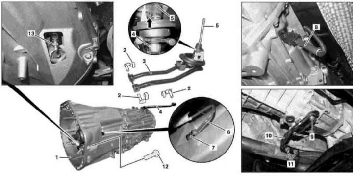
RKPP installation details 716.644 (Models ML 270 CDI)
1 - Carter manual transmission; 2 - Mounting pins; 3 - Connecting lever; 4 - Switching rod; 5 - Switching lever; 6 - Hydraulic line; 7 - Retainer; 8 - Contact connector for electrical wiring of the start enable sensor-switch; 9 - Bolts; 10 - Support bracket for suspension of the exhaust system; 11 - Bolts; 12 - Bolts; 13 - bleed valve
1. Installation details for RKPP 716.644 on ML 270 CDI models are shown in the illustration, which includes all references in the text.
2. Disconnect the negative cable from the battery.
3. Remove the transfer case (see chapter transmission line).
4. Turn out bolts (9 and 11) and remove the support bracket (10) exhaust system suspensions.
5. Once unlocked, remove the pins (2) and separate from the transmission (1) connecting levers (3).
6. Remove pin (2) and separate the shift rod (4) from the lever (5).
7. Remove the retainer (7) and disconnect the hydraulic line (6), - plug the open ends of the line and the nipple connector immediately, taking care not to empty the brake fluid reservoir.
8. Support the transmission assembly (1) cart jack.
9. Turn out bolts (12) while simultaneously jacking the transmission back and down, separate it from the engine.
10. Check the condition of the central clutch operator and pilot bearing in the flywheel. Replace failed components.
11. Check the transmission oil level, which should be approximately 10 mm below the lower cut of the filler hole (measurement can be made with an open end wrench).
12. Installation is carried out in the reverse order - make sure that the stem is connected (4) to the lever (5) the guide on the lever was on the side of the reverse gear lock at the base of the lever assembly (arrow).
13. Finally, bleed the hydraulic circuit of the clutch actuator by releasing air through the valve (13).