



Contents: Removal ↡ Installation ↡
Removal
Note: Due to poor access to the transmission-to-engine mounting bolts, this operation is quite difficult. It is recommended to read the description carefully before attempting this work. Ratchet wrench extensions may be required to access certain bolts.
1. Raise the hood and position a thin sheet of metal (area approximately 300 mm) on the engine compartment bulkhead to protect the bulkhead insulation and hydraulic brake lines from damage when performing the following steps.
2. Disconnect the negative battery terminal.
3. On models with an additional heater, take care not to damage the cooling hose in the engine compartment during work. Loosen the bolt and remove the oil dipstick tube from the cylinder head.
4. Apply the parking brake, then jack up the vehicle and support it on stands (see the section on "Lifting and supporting the vehicle"). The vehicle should be raised high enough to allow the transmission to be pulled out from underneath the vehicle. Where fitted, remove the engine shields as described in Chapter 11.
5. Drain the engine oil as described in paragraph 2.
6. Place a small block of wood between the engine sump and the welded crossmember on the underside of the vehicle.
7. Remove the exhaust system assembly as described in Chapter 4.
8. Where installed, unscrew the bolts and remove the exhaust system heat shields from the underbody of the vehicle to gain access to the intermediate bearing of the propeller shaft.
9. Loosen the bolts and remove the exhaust brackets from the bottom (under the cardan shaft) and from the gearbox (see fig. 6.9).
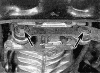
Fig. 6.9. Fastening bolts (shown by arrows) exhaust system brackets to gearbox
10. Disconnect the propeller shaft from the gearbox flange as described in Chapter 8.
11. Loosen the clamp nut on the intermediate bearing of the propeller shaft, then loosen (but don't take it off) intermediate bearing mounting nuts and push the shaft back as far as possible.
12. Support the gearbox using a jack on wheels and an intermediate wooden spacer.
13. Loosen the bolts of the rear powertrain bracket on the gearbox and the bottom of the car and remove the bracket (see fig. 6.13).
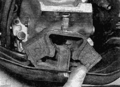
Fig. 6.13. Remove the rear powertrain mount bracket
14. If not already done, remove the bolts and exhaust mounting bracket from the rear of the transmission.
15. Loosen the clamp bolt and pull the speedometer cable out of the transmission, referring to the instructions in the manual if necessary Chapter 12 (see fig. 6.15). Where provided, release the cable from the clamps on the gearbox.
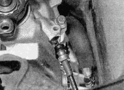
Fig. 6.15 Disconnect the speedometer cable from the gearbox
16. Loosen the bolts and carefully pull the clutch slave cylinder and pipe back to separate the pushrod from the gearbox. Remove the plastic adjusting shim.
Note: On some models, the slave cylinder snot without disconnecting the tube does not provide sufficient clearance to remove the gearbox. In this case, it is necessary to disconnect the hydraulic tube (drain the liquid), leaving the slave cylinder on the gearbox. Place a container under the tube connection to catch any spilled fluid and plug the open ends of the tube and hose.
17. Pry up the retainers and disconnect the gear selector rods from the gear selector lever assembly underneath the vehicle.
18. Remove the starter as described in Chapter 5A.
19. Make sure the transmission is securely supported, then lower the engine as far as possible so that the engine rests on a block of wood between the pan and the crossmember. Be careful not to touch the hydraulic pipes or other components at the rear of the engine bay near the bulkhead, as the cylinder head may rest against the bulkhead.
20. Remove all the transmission-to-engine bolts, leaving one bolt on each side of the transmission. The top bolts are very difficult to access even with the unit suspended. Several ratchet wrench extensions may be required. On some engines (especially on 6-cylinder) the top bolt cannot be unscrewed from below and is more easily accessible with an open-end wrench from the right side after performing the following steps:
- a) Remove the heat shields from around the steering gear housing to gain access to the exhaust system mounting nuts.
- b) Unscrew the mounting nuts and remove the exhaust manifold (rear) from the cylinder head, remove the gasket.
Note the location of the ground bus and all brackets that are held in place by the transmission-to-engine mounting bolts.
21. Once the upper gearbox-to-engine mounting bolts are removed, lift the gearbox so that the power unit is horizontal.
22. Remove the remaining two mounting bolts, then pull the transmission back to separate the input shaft from the clutch. Do not let the transmission hang on the clutch and input shaft, or damage the slave cylinder and hydraulic lines. If necessary, rotate the transmission to the left to separate the top of the bell housing from the car body.
23. Once the input shaft is separated from the clutch, lower the gearbox and lift it out from under the vehicle using a jack on the wheels.
Installation
24. Begin installation by checking the centering of the clutch driven disc as described in Chapter 6.
25. Before installing the gearbox, it is recommended to check the lubrication in the clutch release mechanism as described in Chapter 6.
26. Also check the condition of the centering bearing at the end of the crankshaft as described in Chapter 2.
27. Lubricate the input shaft splines with molybdenum disulfide based grease.
28. Support the transmission with a jack on the wheels and a wooden spacer as for removal. Then, raise the transmission to the required height under the car.
29. Raise the transmission and if the clutch slave cylinder is on the vehicle, raise the tube off the transmission to prevent it from getting pinched when installing.
[Article was obtained from the portal: Mercedesman.ru]
30. Move the gearbox forward, making sure that the input shaft passes through the splines of the driven clutch disc (where required, turn the gearbox to the left so that the gearbox housing does not touch the car body). You may have to rock the engine and transmission slightly, or turn the crankshaft, to insert the input shaft. Do not let the transmission hang on the input shaft.
31. Move the gearbox forward until the bell housing is pressed against the engine. Where necessary, rotate the gearbox to align the engine and gearbox mounting bolt holes.
32. Install and tighten the mounting bolts, making sure the ground bar and all brackets are in place.
33. Further actions are the reverse of those for removal, taking into account the following points:
- a) Install a new exhaust manifold gasket.
- b) Bleed the hydraulic clutch system as described in Chapter 6.
- c) Connect the propeller shaft to the gearbox flange as described in Chapter 8.
- d) Install the exhaust system as described in Chapter 4.
- d) Fill the gearbox with oil as described in paragraph 2.