
Warning: Clutch lining wear dust that coats clutch parts may contain asbestos, which is hazardous to health. Do not blow it off with compressed air or inhale it. Do not use gasoline or other gasoline-based solvents to wash off dust. Use brake cleaner or methylated spirits to flush dust into a suitable container. Then wipe the coupling parts with clean rags and put them in a closed labeled container.
Removing
1. Remove the gearbox as described in Chapter 7A.
2. If to be installed "native" Clutch Make an alignment mark between the clutch housing and the flywheel to allow the clutch to be reinstalled correctly.
3. Gradually unscrew the bolts securing the clutch housing to the flywheel and remove the washers
4. Remove the clutch housing from the flywheel (see fig. 2.4). Be prepared to catch the clutch disc that may fall out when you remove the clutch housing, and determine which side the disc is installed on - usually the two sides of the disc are indicated "Engine side" (engine side) And "Transmission side" (gear side). The side of the hub with the larger protective side, facing away from the flywheel.
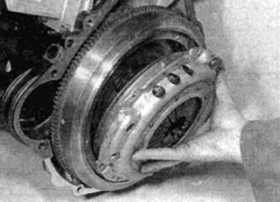
Pic. 2.4. Removing the clutch housing from the flywheel
Examination
5. With the clutch removed, use a dry cloth to remove all traces of dust. Despite. that at present most friction linings do not contain asbestos, some do, and it would be wiser to take protective measures; asbestos dust is hazardous to health and should not be inhaled.
6. Check up a condition of friction slips of a conducted disk. Look for worn or loose rivets. Check disc for warpage, cracks, broken damper springs (where they are installed) and worn splines. The surface of the friction linings may have a shiny appearance, but if the friction material is visible everywhere, this is acceptable. If traces of oil contamination are found, which have the form of a continuous or partial shiny layer, the disc should be replaced. Before. how to install new clutch parts, you should determine the source of contamination and eliminate it. Usually oil leaks from under the rear crankshaft seal or gearbox input shaft seal (replacement is described in Chapters 2 and 7A, respectively). The disk should be replaced if the lining thickness has decreased below or slightly above the level of the rivet heads. Recall that the wear of the driven disk can be checked without removing the clutch and gearbox from the car - see chapter 1.
7. Check the surfaces of the flywheel and pressure plate. If grooves or severe scuffing are found, replacement is necessary. The pressure plate should be replaced if cracks are found or if the diaphragm spring is damaged or weakened.
8. With the clutch removed, it is recommended to check the condition of the release bearing as described in paragraph 3.
9. Check up the aligning bearing in an end face of a cranked shaft. Make sure it rotates smoothly without noise. If the mating surface of the gearbox input shaft is worn or damaged, install a new bearing as described in the appropriate part chapter 2.
Installation
10. If new parts are being installed, where it is applied, remove all anti-corrosion grease from the friction surfaces on the disc and the contact surface on the pressure plate.
11. It is important to ensure that oil or grease does not get on the lining of the driven plate or on the surfaces of the pressure plate and flywheel. It is recommended to install the clutch with clean hands and wipe the surfaces of the pressure plate and flywheel with a clean cloth before starting work.
12. Apply molybdenum grease to the driven disc hub splines, then place the disc against the flywheel with the side of the hub with the larger protective surface away from the flywheel (most pressure plates have a label "Engine side" (engine side), which should face the flywheel) (see fig. 2.12). Hold the driven plate against the flywheel until the clutch basket is in place.
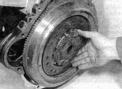
Pic. 2.12. Install the driven disc with the larger side of the hub facing away from the flywheel
13. Install the clutch housing, matching the marks on the flywheel and clutch housing where required. Check that the clutch basket is installed on the keys on the flywheel. Insert the mounting bolts and washers, then tighten them by hand so that the driven disk is clamped, but it can still be moved.
14. After that, you can center the driven disk so that after connecting the engine and gearbox, the splines of the input shaft of the gearbox pass through the splines in the hub of the driven disk.
15. Centering can be done by inserting a round bar or long screwdriver into the hole in the center of the driven disk so that the end of the bar rests on the centering bearing at the end of the crankshaft. If possible, use a blunt tool, however, if using a screwdriver, wrap adhesive tape around the blade to prevent damage to the bearing surface. By moving the bar from side to side, move the driven disk as far as necessary to achieve centering. With the bar removed, inspect the disc hub in relation to the hole in the end of the crankshaft and the circle formed by the ends of the fingers of the diaphragm spring. When the hub is exactly in the center, the centering will be done. You can use a centering tool, it is easier and eliminates the need for visual alignment control (see fig. 2.15).
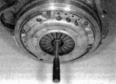
Pic. 2.15. Centering the driven disk using a tool
16. Gradually, in a diagonal sequence, tighten the clutch basket mounting bolts with the required torque. Remove the alignment tool.
17. Install the gearbox as described in Chapter 7A.