
2. The check is performed below the clutch slave cylinder and requires the use of a special tool that can be easily made from a strip of metal according to the sketch shown (see fig. 33.2).
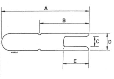
Pic. 33.2. Measuring device for determining the wear of the driven clutch disc
- A - 55.0 mm
- H - 26.0 mm
- C - 7.0 mm
- D - 14.0 mm
- E - 12.0 mm
3. After manufacturing the measuring fixture, do the following.
4. Apply the parking brake, then jack up the front of the vehicle and place it on jack stands (see "Lifting the vehicle and placing it on stands").
5. Insert the fork of the tool into the gap between the slave cylinder flange and the clutch bell housing.
6. Push the tool until the fork rests against the pusher of the working cylinder.
7. If the two recesses on the fixture are not visible, then the driven disc linings are in satisfactory condition. If both notches are visible, then the pads have reached a critical thickness and the clutch assembly must be replaced (see fig. 33.7, a, b).
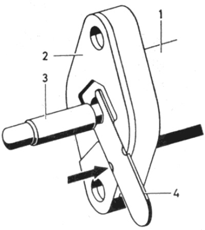
Pic. 33.7, a Checking the wear of the clutch disc - the linings are in a satisfactory condition
1 working cylinder
2 Adjusting lining of the working cylinder
3 Pusher
4 Measuring fixture
The arrow points to fixture notches that are not visible
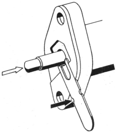
Pic. 33.7, b Checking the wear of the clutch disc - the lining is worn
Light arrow - Movement of the pusher when worn
Dark arrow - Notches on fixture are visible
8. At the end of the test, remove the tool and lower the vehicle to the ground.