
Warning: Clutch lining wear dust that coats clutch parts may contain asbestos, which is hazardous to health. Do not blow it off with compressed air or inhale it. Do not use petrol or other non-petrol solvents to wash off dust. Use brake cleaner or methylated spirits to flush dust into a suitable container. Then wipe the coupling parts with clean rags and put them in a closed labeled container.
Release bearing
Removing
1. Remove the gearbox as described in Chapter 7A.
2. Rotate the bearing to separate it from the release fork, then pull the bearing forward and remove it from the guide bushing in the transmission bell housing (see fig. 3.2).
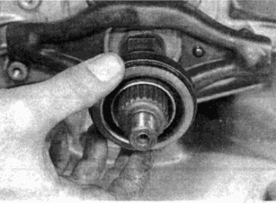
Pic. 3.2. Removing the clutch release bearing
Examination
3. Turn the release bearing and check for ease of rotation. Hold the outer race and try to move it lengthwise against the inner race. If play or seizing is found, replace the bearing. When installing a new clutch, the release bearing must be replaced.
Installation
4. Clean and then lightly grease the release bearing surfaces in contact with the release lever. Similarly, lubricate the guide bushing.
5. Slide the bearing into place on the guide bushing, then rotate it until it snaps into place on the release lever.
6. Install the gearbox as described in Chapter 7A.
Release lever
Removing
7. Remove the release bearing as described earlier.
8. Pull the release lever forward on the slave cylinder side, then move the lever to the side to release it from the axle and remove the lever from the top of the guide bush (see fig. 3.8)
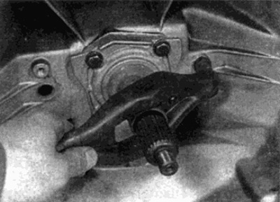
Pic. 3.8. Removing the clutch release lever
Examination
9. Check the wear on the surfaces of the clutch release lever in contact with the release bearing, axle and pusher of the working cylinder. If wear is found on the lever, replace it.
10. Check up a condition of a spring ring of fastening of the lever of deenergizing of coupling, if necessary the lever.
Installation
11. Clean and lightly grease the contact surfaces of the release bearing on the release lever and axle. Similarly, lubricate the guide bush (see fig. 3.11).
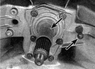
Pic. 3.11. Lubricate pivot pin and guide bushing (shown by arrow)
12. Move the clutch release lever into place on top of the guide bushing, then move the lever pins onto the pivot pin, making sure the mounting circlip is seated around the rear end of the axle (see fig. 3.12).
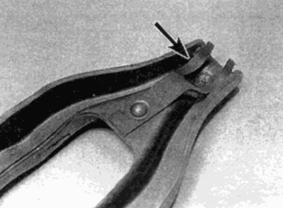
Pic. 3.12. Make sure the snap ring (shown by arrow) fixed axis of rotation
13. Install the release bearing as described above.