
| Total information | |
| Type | 5-speed automatic with electronic shift control |
| Designation | |
| 722.661 |
| 722.666 |
| 722.660 |
| 722.662 |
| 722.674 |
| 722.663 |
| Type and volume of ATF | See Specifications for Chapter Ongoing care and maintenance. |
| Codes of diagnostics of system of electronic control of automatic transmission see the Chapter Engine Electrical Systems. | |
| Gear ratios and actuation scheme of AT 722.6 activators | |||||||||
Broadcast | gear ratio | IN 1 | AT 2 | AT 3 | K1 | K2 | K3 | F1 | F2 |
1 | 3.93:1 | X* | X | X* | X | X | |||
2 | 2.41:1 | X | X | X* | X | ||||
3 | 1.49:1 | X | X | ||||||
4 | 1.00:1 | X | X | ||||||
5 | 0.83:1 | X* | X | X | |||||
N | X | X | |||||||
R (mode S) | -3.10:1 | X* | X | X | X | ||||
R (W mode) | -1.90:1 | X | X | X | |||||
* Switch activators only in kickdown mode | |||||||||
| Codes for diagnostics of the automatic transmission electronic control system, retrieved using an OBD II scanner | |||||||||
Refer to the Specifications for the Chapter Engine Electrical Systems. | |||||||||
| Tightening force of threaded connections, Nm | |||||||||
| Shift rod head bolt | 12 | ||||||||
| Transmission oil pan drain plug | 20 | ||||||||
| Bolts of fastening of the pallet to a crankcase | 8 | ||||||||
| Bolts for securing the heat shield to the transmission housing | 8 | ||||||||
| Bolts for fastening the electro-hydraulic control unit to the transmission housing | 8 | ||||||||
| Bolts of fastening of assembly of the lever of the selector to the panel of a floor | 6 | ||||||||
At the moment of pulling away, the automatic transmission (AT) acts as an ordinary clutch, and during the movement it performs the work of shifting gears. All models considered in this Manual are equipped with AT series 722.6.
The main nodes of the AT are: torque converter (torque converter), planetary gear and hydraulic or electronic control unit. To switch to another gear ratio in the planetary gearbox, hydraulic disc brakes and disc clutch are used. The design of a typical AT is shown in the illustration.
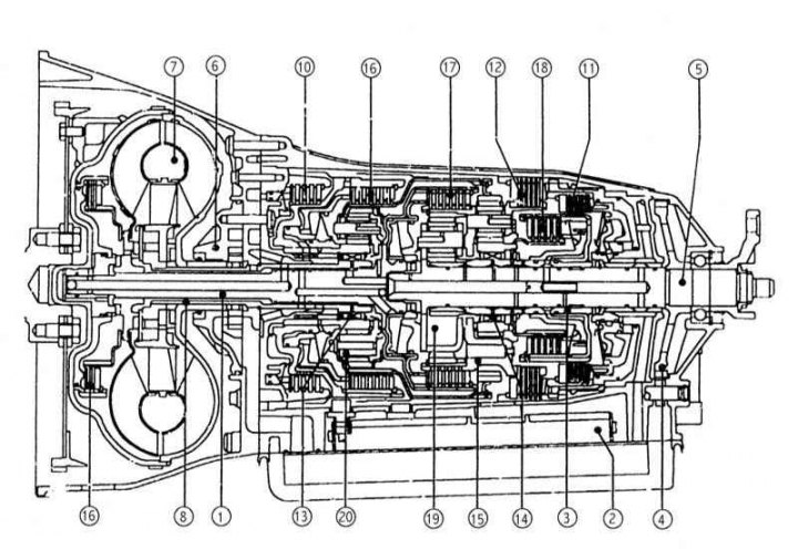
The design of a typical AT
1 - Input shaft; 2 - Electro-hydraulic switching control unit; 3 - Intermediate shaft; 4 - Parking lock gear; 5 - Output shaft; 6 - Oily (ATF) pump; 7 - Torque converter; 8 - Reactor shaft; 9 - Locking clutch of the torque converter; 10 - Multi-disc brake assembly B1; 11 - Multi-disc brake assembly B2; 12 - Multi-disc brake assembly B3; 13 - Overrunning clutch F1; 14 - Overrunning clutch F2; 15 - Rear planetary assembly H; 16 - Multi-disc clutch K1; 17 - Multi-disc clutch K2; 18 - Multi-disc clutch K3; 19 - Central planetary assembly M; 20 - Front planetary assembly V
The torque converter has the same function as a hydraulic clutch. Its task is to carry out the clutch when starting off and shifting gears.
transmission control system (also known as electronic synchronous shifting system) is an integral part of the modified engine management system, installed only on models with AT. The control system can work in a special emergency (safe) mode with a limited switching range, which switches to when a malfunction is detected (a special control lamp is activated on the instrument panel (see chapter Controls and techniques for safe operation). Switching to emergency mode allows you to drive the car under its own power to a service station for detailed diagnostics and necessary remedial repairs. Based on the analysis of data coming from various information sensors (not necessarily directly related to the functioning of the actual transmission), transmission control module (TCM) selects the optimal mode of operation of the AT from the point of view of efficiency, smooth switching, etc. At certain throttle positions, the TCM can command the torque converter to lock up, limiting AT shifts to only 4th and 5th gears, resulting in significant fuel economy.
The only AT maintenance procedure that should be performed on a regular basis is checking the working fluid level (ATF), the procedure for which is described in Chapter Ongoing care and maintenance. There is no need for regular ATF replacement.
An ATF cooler is installed next to the radiator of the engine cooling system.
Based on input from the traditional under-throttle kickdown switch, the TCM shifts the transmission to the adjacent gear currently in use when the pedal is fully depressed, which can significantly improve the vehicle's dynamic performance, such as during overtaking.
There are several modes of operation of the transmission, each of which can be engaged after moving the selector to one of the following positions: «P», «R», «N», «D», «1», «2», «3», «4» (contact the head Controls and techniques for safe operation). Starting from 09/01/99, electronic selector modules with the function of sequential selection of driving mode ranges began to be installed on all models «D» (1, 2, 3 and 4), when the transfer of AT to the mode of limited switching ranges (4, 3, 2 and 1) carried out by lateral push-ups of the lever (D+/D-) (see Section Getting started and shifting gears).
Thanks to the use of a special sensor-switch N / P, the engine can only be started when the selector lever AT is in the position «R» or «N», which helps prevent accidental starting of the car when trying to start.
This Chapter discusses only the most common maintenance procedures for AT, which lie within the qualifications of an average amateur mechanic.