
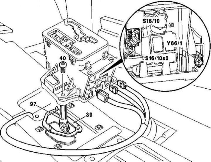
Details of installation of the selector module on models produced before 08/31/99 (without the function of sequential switching of ranges of motion)
39 - Sealing gasket; 40 - Bolts (4 things); 97 - Intermediate lever; S16 / 10 - AT position sensor; S16 / 10s2 - Sensor-switch for reversing lights; Y66 / 1 - E / m activator of blocking shifts R / P
1. On models manufactured before 08/31/99, a selector module is installed without the function of sequential switching of ranges of motion. The details of the module installation are shown in the illustration, to which all references in the text refer.
2. Disconnect the shift drive rod from the intermediate lever (97).
3. Remove the insulating mat.
4. Remove 4 bolts (40).
5. Disconnect the electrical wiring from the sensors-switches (S16/10 and S16/10s2) and an electromagnetic activator for blocking switching R / P.
6. Remove the selector module, check the condition of its sealing gasket (39), - replace if necessary.
7. Installation is carried out in the reverse order - make sure that the gasket is installed correctly (39).
8. Finally, clear the memory of the on-board self-diagnosis module (see chapter Engine Electrical Systems).
Release models from 09/01/99
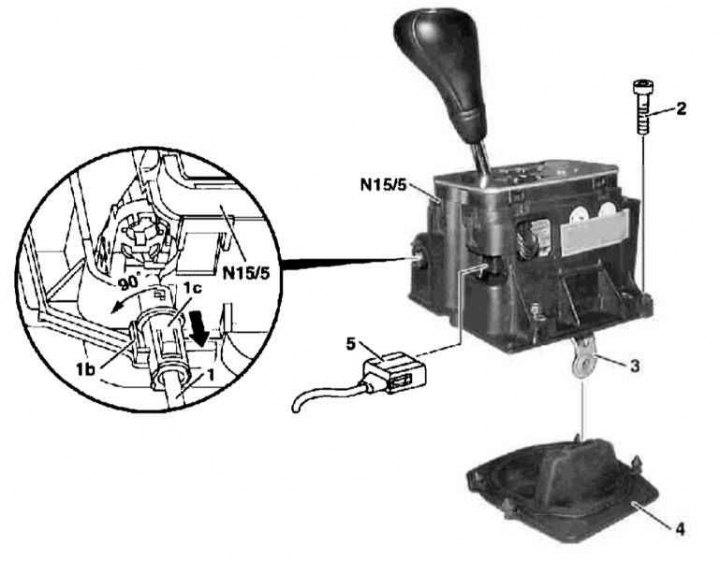
Installation details of the electronic selector module on models manufactured from 09/01/99 (with the function of sequential switching of ranges of motion)
1 - Electronic ignition switch lock cable (EIS); 1b - Locking tongue; 1c - Connector; 2 - Allen wrench bolts (3 pcs); 3 - Intermediate lever; 4 - Sealing gasket; 5 - Contact connector for electrical wiring; N15/5 - Electronic selector module
1. On production models from 09/01/99, an electronic selector module with the function of sequential switching of ranges of motion is installed (see chapter Controls and techniques for safe operation). The details of the module installation are shown in the illustration, to which all references in the text refer.
2. Disconnect draft of a drive of switching АТ from the intermediate lever (3).
3. Remove the center console
4. Remove the insulating mat.
5. Press out the locking tab (1b), turn the connector (1s) 90°in the direction of the arrow and pull to disconnect the EIS lock cable (1) from the selector module (N15/5)
6. Remove 3 bolts (2).
7. Disconnect the wiring connector (5).
8. Remove selector module (N15/5), check the condition of its sealing gasket (4), - replace if necessary.
9. Installation is carried out in the reverse order - follow the correct installation of the sealing gasket. When connecting the EIS lock cable (1) make sure the ignition switch is in position «0». Make sure that the blocker is functioning properly, - the selector lever is taken out of the position «R», must be enabled only with the foot brake pedal depressed and in the position «2» the ignition switch, removing the key from the lock should only be possible in the «R» selector lever.
10. Finally, clear the memory of the on-board self-diagnosis module (see chapter Engine Electrical Systems).