
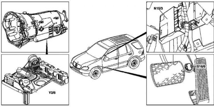
The layout of the components of the electronic control system AT
N15/3 - Transmission control module (TCM); S16 / 6 - Sensor-switch for activation of the kickdown mode; Y3/6 - Electrical assembly of the electro-hydraulic shift control unit
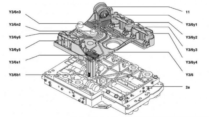
Design of the electro-hydraulic shift control unit
2a - Hydraulic block; 11 - 13-pin connector; Y3/6 - Electrical control unit for switching; Y3/6b1 - ATF temperature sensor; Y3 / 6n2 - Sensor 2 revolutions; Y3 / 6n3 - Sensor 3 revolutions; Y3 / 6s3 - Start blocking contact; Y3/6y1 - E/m pressure modulation control valve; Y3/6y2 - Solenoid valve for switching pressure control; Y3 / 6y3 - Solenoid valve for controlling shifts 1-2 and 4-5; Y3 / 6y4 - Solenoid valve for switching control 3-4; Y3 / 6y5 - Solenoid valve for switching control 2-3; Y3/6y6 - Solenoid valve PWM torque converter lock-up
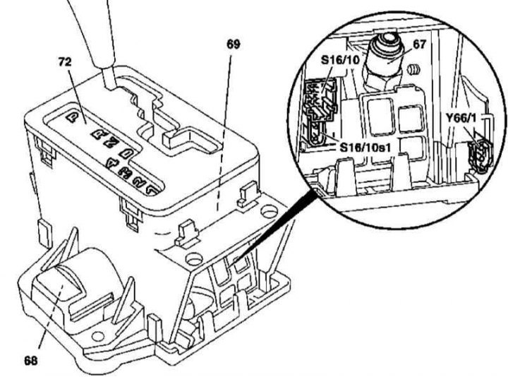
Selector module design (without sequential range selection, - models of release through 08/31/99)
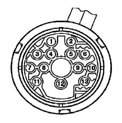
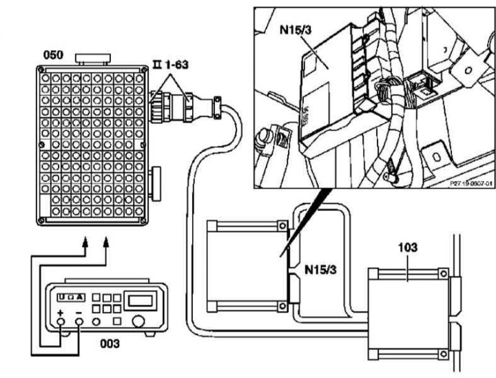
Terminal identification card for the 13-pin connector of the electro-hydraulic shift control unit
1 - Sensor 3 revolutions (Y3/6n3); 2 - Solenoid valve for modulating pressure adjustment (Y3/6y1); 3 - Sensor 2 revolutions (Y3/6n2); 4 - Temperature sensor input (Y3/6b1) and starter interlock contact (Y3/6s1); 6 - Supply voltage e / magnetic valves; 7 - Sensor supply voltage; 8 - E / magnetic valve for shifting gears 2-3 (Y3/6y5); 9 - E / magnetic valve for shifting gears 3-4 (Y3/6y4); 10 - Solenoid valve for adjusting the switching pressure (Y3/6y2); 11 - E / magnetic valve (rotation transducer blocking) (Y3/6y6); 12 - Sensor body; 13 - Solenoid shift valve 1-2/4-5 (Y3/6y3)
TCM (N15/3) determines the current operating parameters of the vehicle and performs sequential shift control based on the ease of shifting and driving parameters.
Activation of the switching solenoid valves is carried out at the command of the ETC control unit (N15/3). The required pressure value is calculated on the basis of the input data and the necessary correction adjustment of the transmitted torque.
Processed parameters
Illustrative material on the principle of data exchange in the AT control system is shown in the illustration.
Input and output signals of the control unit AT 722.6 and CAN data bus
N15/3 - TCM; Х11/4 - DLC connector; Y3/6b1 - ATF temperature sensor; Y3/6n2 - Speed sensor 2; Y3/6n3 - Speed sensor 3; Y3 / 6s3 - Starter blocking contact; Y3 / 6u1 - Solenoid valve for controlling pressure modulations; Y3 / 6u2 - E / m switch pressure control valve; Y3 / 6u3 - E / m valve switching 1-2 and 4-5; Y3 / 6u4 - E / m switching valve 3-4; Y3 / 6u5 - E / m switching valve 2-3; Y3 / 6u6 - E / m PWM valve for blocking the torque converter; A1 - Instrument cluster; CAN - Network bus of the engine compartment; N3/10 - ECM ME-SFI; N3/9 - ECM CDI; N15/3 - TCM; N15/5 - Electronic selector module; N47 - ETS control module; N73 - EIS electronic ignition switch control module
ME-SFI control unit (N3/10) /CDI (N3/9)
- Torque developed by the engine;
- Gear shift;
- Emergency mode;
- The functioning of the tempostat;
- Activation of the speed limit system;
- Starter operation;
- Activation of the kickdown mode;
- Engine operating parameters.
Electronic selector module (N15/5)
- Selector lever position;
- Transmission mode switch (S16/5);
- Kickdown activation switch (S16/6).
ETS control unit (N47)
- Wheel speed;
- Torque of brake mechanisms;
- The fact of squeezing the foot brake pedal;
- Parking brake status.
EIS control unit (N73)
- Condition of contact terminals;
- transmission option.
Instrument cluster (A1)
- Selector lever position/selected gear.
ETS control unit (N47)
- transmission option;
- Information about the selected transfer.
ME-SFI control unit (N3/10) /CDI (N3/9)
- Torque developed by the engine;
- Emergency mode;
- Activation of the driving mode;
- Selector lever position P/N;
- Transmission mode switch (S16/5);
- transmission option.