
Sequentronic Control Unit Analog Inputs
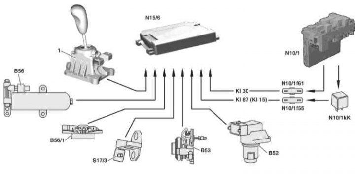
a - Working food; s - Control power; B56 - Automated gearbox pressure sensor; B56 / 1 - Transmission detection sensor; S17 / 3 - Contact sensor-switch of the left front door; B53 - Clutch travel sensor; B52 - Clutch speed sensor; Cl. 87 (Cl. 15) - Power supply circuit 87 from relay circuit 87, chassis (N10/1kK) to the front SAM control unit (N10/1), protected by fuse 55 (N10/1f55); Cl. 30 - Power supply circuit 30 from the front SAM control unit (N10/1), protected by fuse 61 (N10/1f61); 1 - Sequential gear selection switch
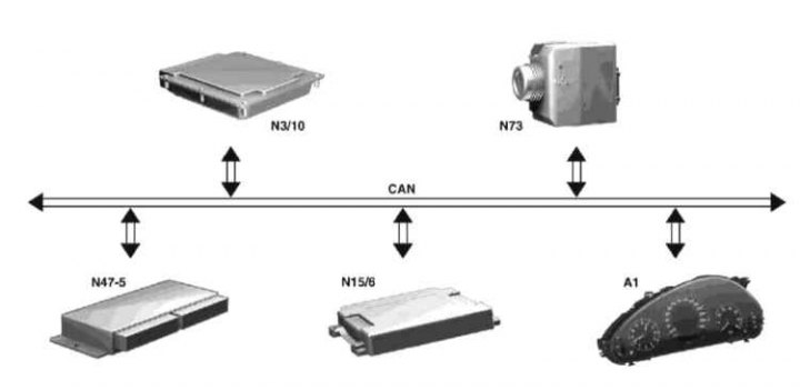
Data exchange of control units via switched data bus CAN
Sequentronic Control Unit Analog Outputs
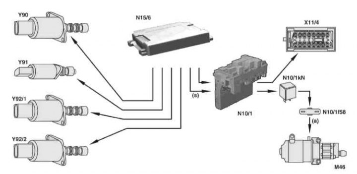
Y90 - Hydraulic clutch release valve; Y91 - Transmission brake solenoid valve; Y92/1 - Solenoid valve switching 1, 3, and 5; Y92/2 - Solenoid valve switching R, 2, 4 and 6; Х11/4 - DLC connector via SAM control unit (N10/1); M46 - ASG hydraulic pump via ASG control relay (N10/1kN) in the SAM control unit (N/10/1), protected by fuse 58 (N10/1f58); Connection possible via engine bay CAN bus (CAN C): A1 - Dashboard; N3/10 - ME-SFI control unit; N3/9 - CDI control unit; N47-5 - ESP / BAS control unit; N73 - EIS control unit [EZS]
Analog output signals
Purpose of the gearbox shift control unit (N15/6):
- Definition of operating states;
- Processing of incoming CAN signals;
- Calculation of working variables;
- Activation of executive devices;
- Saving and issuing diagnostic data;
- Processing of incoming analog signals.
Only the N15/6 control unit is capable of calculating the shift parameters based on the analysis of analog signals coming from the information sensors for determining the selected gear, clutch speed, clutch travel, shift request and hydraulic pressure.
The 12+2-pin and 18-pin connector of the control unit is fixed with safety clips.
The main control functions of the ASG are stored in the ECU's modular programming code, where each task is separated into a separate block. However, the interdependencies that take place determine the connectivity of the network functioning.
The block circulation period is determined by the processor frequency and is approximately 10 ms.
Information transmitted by the transmission shift control unit (N15/6) via CAN bus
ME-SFI control unit (N3/10) /CDI (N3/9):
- Emergency stop of the engine;
- Current transfer;
- Required transfer;
- Transmission emergency operation mode;
- Creeping torque;
- Switching to manual control mode;
- Dashboard (A1):
- Current transfer;
- transmission mode;
- Error/failure messages.
ESP/BAS control unit (N47-5):
- transmission option;
- Current transfer;
- Required transfer.
Information received by the transmission shift control unit (N15/6) with CAN bus
Dashboard (A1):
- Opening / closing the driver's door;
- Outside air temperature.
ME-SFI control unit (N3/10) /CDI (N3/9):
- Pedal position;
- Emergency mode;
- The functioning of the tempostat;
- idle speed;
- Speed limiter activation;
- Activation of the engine speed limiter;
- Inertial cut-off of fuel supply;
- Engine torque;
- Oil temperature.
Front SAM control unit (N10/1):
- wake-up function;
ESP/BAS control unit (N47-5):
- Wheel speed;
- Brake light switch;
- Parking brake;
- Signal for the ESP control unit.
EIS control unit (N73):
- The state of the contact terminals.