
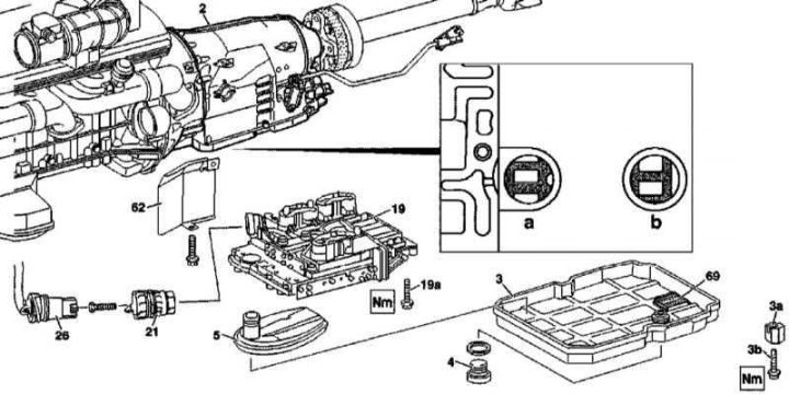
Details of the installation of the electro-hydraulic control unit for switching AT 722.6 (on the example of a rear-wheel drive model)
2 - Transmission housing; 3 - Oil pan; 3a - Retainer; 3b - Bolt (TORX); 4 - Drain plug of the oil pan AT; 5 - ATF filter; 19 - Electro-hydraulic switching control unit; 19a - Bolt (TORX); 21 - Guide sleeve; 26 - 13-pin connector; 62 - Heat shield; 69 - Magnet; a - Socket for landing speed sensor 3 (Y3/6n3); b - RPM sensor socket 2 (Y3/6n2)
1. Details of the installation of the electro-hydraulic switching control unit AT 722.6 are shown in the illustration, to which all references in the text refer.
2. Jack up the car and put it on stands.
3. Remove the key from the ignition switch.
Note. On models equipped with the Keyless Go system, by pressing the Start-Stop button, turn off the ignition, remove the smart card from the car and move it out of the transmitter's sensitivity range.
4. Move the shift actuator lever on the transmission housing to position «R» (see illustration The design of the switching drive AT).
5. Remove the trim panels of the engine compartment, unbolt the support bracket from the rear panel.
6. Remove the heat shield (62) and disconnect the 13-pin electrical connector (26).
7. Release the AT from the crankcase and remove the guide bush (21).
8. Removing the cork (4), drain the ATF from the AT crankcase, - do not forget to replace the sealing washer, if necessary (if the oil is contaminated) Flush lines of a path of cooling ATF.
9. Turn out fixing bolts and remove the pallet of a case of transmission (3).
10. Remove the magnet from the pallet (69) and clean it of adhering metal filings.
11. Remove the ATF filter (5).
12. Turn out a bolt (19a) and remove the electro-hydraulic shift control unit (19).
13. Installation is carried out in the reverse order - make sure that the crankcase is filled with transmission fluid correctly.