
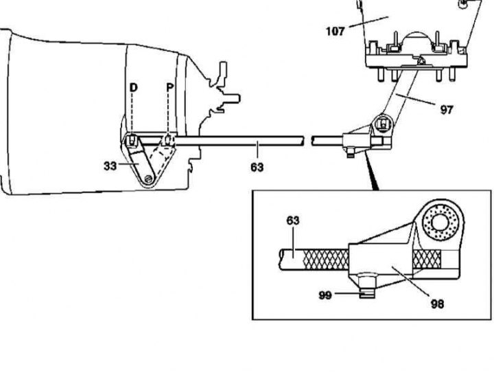
The design of the switching drive AT
33 - Executive lever; 63 - Shift rod; 97 - Intermediate lever; 98 - Thrust head; 99 - Bolt; 107 - Base selector assembly
1. The design of the AT switching drive is shown in the illustration, to which all references in the text refer.
2. Drive the car onto the lift, raise and level it strictly horizontally.
3. Move the actuating lever (33) into position «D» and ask the assistant to hold it in this position during the entire procedure.
4. Connect the rod head (98) to intermediate lever (97) and secure it with clips.
5. Fill up the thrust (63) into the head, connect it to the lever (33) and secure with fasteners.
6. Pressing the head (98), tighten the bolt (99), - make sure that the thrust (63) and head (98) did not turn, but the lever (33) stayed in position all the time «D».
7. Check up correct functioning of a drive.