



Note: Individual characteristics are also given in the text of the Chapter and, if their implementation is mandatory, are highlighted in bold.
General parameters
| Type | 5-speed, electronic gear shift control |
| Designation | 722.5 or 722.6 |
| Gear ratios 722.6 | |
| S500 | |
| 1st gear | 3.59: 1 |
| 2nd gear | 2.19: 1 |
| 3rd gear | 1.41: 1 |
| 4th gear | 1.00: 1 |
| 5th gear | 0.83: 1 |
| Reverse gear | 3.16: 1 |
| Main gear | 2.82: 1 |
| S320 | |
| 1st gear | 3.93: 1 |
| 2nd gear | 2.41: 1 |
| 3rd gear | 1.49: 1 |
| 4th gear | 1.00: 1 |
| 5th gear | 0.83: 1 |
| Reverse gear | 3.16: 1 |
| Main gear | 3.07: 1 |
| ATF type | Cm. Specifications to the Chapter Routine maintenance |
| ATF volume, l | Cm. Specifications to the Chapter Routine maintenance |
| Pressure in the hydraulic system AT 722.5 | |
| Vacuum modulator | black |
| Modulating pressure, Bar | 4.0 |
| Working pressure, Bar | 14.4±1 |
| Pressure in the centrifugal regulator, Bar | |
| At a speed of 30 km/h | 0.90 |
| At a speed of 56 km/h | 2.30 |
| Torque converter diameter, mm | 270 |
Tightening force of threaded connections, Nm
722.5
| Drain plug in the transmission pan | 22 |
| Torque converter drain plug | 14 |
| Torque converter mounting bolt to the base plate | 42 |
| Vacuum unit mounting bolt | 8 |
| Bolt for fastening the secondary pump to the crankcase AT | 8 |
| Secondary pump mounting bolt to the front cover | 20 |
| Rear cover mounting bolt | 13 |
| Output shaft flange fastening nut | 120 |
| Overload protection sensor | 70 |
| Bolt for fastening flange K2 to AT crankcase | 11 |
722.6
| Torque converter drain plug | 16 |
| Torque converter mounting bolt to the M8 drive disk | 42 |
| Drain plug in the transmission pan | 20 |
| Propeller shaft mounting nut to the M12 gearbox | 60 |
| Solenoid valve mounting bolt to the gear shift plate | 8 |
| Valve body cover mounting bolt to the valve body M6x30 | 8 |
| Bolt for fastening the side cover to the cover valve bodies and valve bodies M4x12 | 4 |
| Transmission housing mounting bolt to the torque converter housing | 20 |
| Bolt for fastening the pan to the transmission housing | 8 |
| Output shaft flange fastening nut | 200 |
| Bolt for fastening the electrohydraulic control unit to the transmission housing | 8 |
| Multi-disc mounting bolt b2 brakes to transmission housing | 16 |
| Bolt securing the pawl to the selector lever gear shifting | 8 |
| Selector lever mounting bolt gear shift to body | 6 |
13-pin transmission connector pin assignment
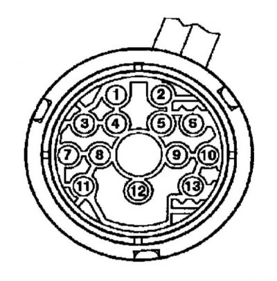
| 1 | Sensor 3 revolutions (Y3/6n3) |
| 2 | Solenoid valve for modulating pressure regulation (Y3/6y1) |
| 3 | Sensor 2 revolutions (Y3/6n2) |
| 4 | Input signal from temperature sensor (Y3/6b1) and starter interlock contact (Y3/6s1) |
| 5 | — |
| 6 | Supply voltage of electromagnetic valves |
| 7 | Sensor supply voltage |
| 8 | 2-3 Shift Solenoid Valve (Y3/6y5) |
| 9 | 3-4 Shift Solenoid Valve (Y3/6y4) |
| 10 | Solenoid valve for switching pressure regulation (Y3/6y2) |
| 11 | Electromagnetic valve (rotation converter locks) (Y3/6y6) |
| 12 | Sensor housing |
| 13 | 1-2/4-5 Shift Solenoid Valve (Y3/6y3) |