



The main components of the AT are: torque converter (torque converter), planetary gearbox and hydraulic or electronic control system. To change the gear ratio in the planetary gearbox, hydraulically driven disc brakes and disc clutch are used.
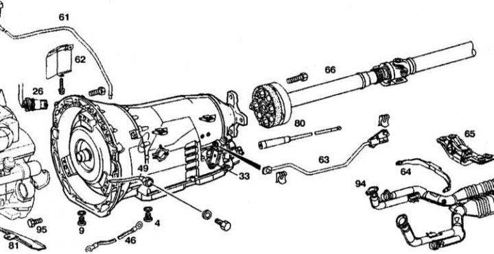
Typical AT design
1 - Transmission oil filler tube; 2 - Shield; 3 - 13-pin connector; 4 - Transmission; 5 - Cardan shaft flange; 6 - Parking position lock; 7 - Selector rod; 8 - Exhaust system; 9 - Exhaust system bracket; 10 - Crossbar with support; 11 - Ground connection bus
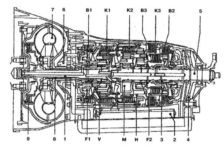
Automatic transmission section
1 - Input shaft; 2 - ECU; 3 - Intermediate shaft; 4 - Parking lock gear; 5 - Output shaft; 6 - Oil pump; 7 - Torque converter; 8 - Reactor shaft; 9 - Torque converter lock-up clutch; B1 - Multi-disc brake assembly B1; B2 - Multi-disc brake assembly B2; B3 - Multi-disc brake assembly B3; F1 - Flywheel F1; F2 - Flywheel F2; H - Rear planetary assembly; K1 - Multi-disc clutch K1; K2 - Multi-disc clutch K2; K3 - Multi-disc clutch K3; M - Central Planetary Assembly; V - Front planetary assembly
The torque converter functions like a hydraulic clutch. Its job is to provide clutch when starting off and changing gears.
Transmission control system (known as electronic synchronous switching system) is an integral part of a modified engine management system, installed only on models with automatic transmission.
Layout diagram of electronic components of the control system
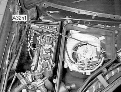
Location of the AT control unit (N15/3). In the engine compartment, on the right side near the bulkhead
The control system can operate in a special safe mode, which it switches to when any malfunction is detected. In this case, the transmission operating modes are limited, and the car can be driven to a repair shop under its own power. When the control system switches to safe mode, a control lamp lights up on the instrument panel (refer to Chapter User manual).
By analyzing information coming from various sensors (not only sensors that are directly related to the transmission), the control system selects the optimal gearbox operating mode in terms of economy, smoothness, etc. At a certain position of the throttle valve, the control system can block the torque converter in such a way that only the fourth and fifth gears are engaged. This achieves a significant reduction in fuel consumption.
The only regular maintenance procedure for the box is checking the level of the working fluid (see section Checking fluid levels, leak control Chapters Routine maintenance). There is no need to change the transmission fluid regularly.
A transmission fluid cooler is installed next to the cooling system radiator.
There is no traditional kickdown switch. The mode is activated directly by the transmission control system after processing information from the throttle position sensor.
There are several transmission operating modes, each of which can be engaged by moving the selector to one of the following positions: "P", "R", "N", "D", "1", "2", "3", "4" (refer to Chapter User manual).
The engine can only be started if the selector is in the "P" or "N" position. This is done to prevent the car from moving when trying to start it (if the selector is set to one of the other positions). By analyzing the information coming from the sensors, the control system allows or prohibits the engine from starting. The locations of the various relays are indicated in Chapter On-board electrical equipment).