
Brake caliper
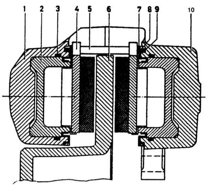
1, 10 - bracket; 2 - piston; 3 - sealant; 4 - brake shoe; 5 - fastening pin; 6 - brake disc; 7 - heat-shielding cap; 8 - retaining ring; 9 - anther
Removing the wheel brake
Front wheel brake
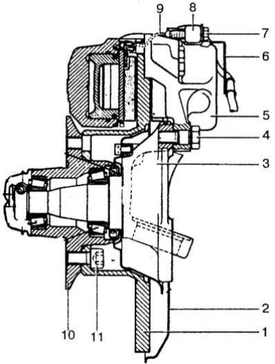
1 - brake disc; 2 - protective cover; 3 - rotary fist; 4 - self-locking bolt; 5 - brake caliper; 6 - wire holder; 7 - bolt; 8 - connector; 9 - sensor fastening clamp; 10 - front wheel hub; 11 - self-locking bolt
1. Prepare the vehicle and remove the desired front wheel.
2. Remove the brake pads (as stated before).
3. Unscrew the cover of the brake fluid reservoir of the main brake cylinder, place a polyethylene sheet gasket under it, tightly screw the cap in order to reduce fluid loss during further operations.
4. Turn away a bolt of fastening of the gauge of wear of pads from a support.
5. Loosen the brake hose connection on the brake caliper.
6. Turn out bolts of fastening and remove a brake calliper from a rotary fist, turn away nipple connection of a flexible hose.
7. To remove the brake mechanism of the rear wheels, the operations are carried out in the same way, only lift the rear of the car and remove the brake caliper from the wheel hub.
Disassembly
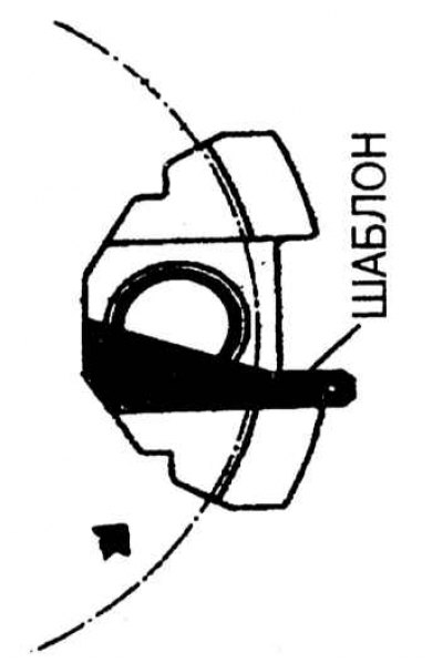
Groove position control
1. Remove the dust caps, but be careful not to damage the pressed ring.
2. Using air pressure from a tire pump connected to the hydraulic inlet on the brake caliper, extend one of the pistons while holding the opposite piston.
3. By blocking the hole of the removed piston (thick rubber), extend the second piston in the same way.
4. Mark the pistons and corresponding cylinders so that they are not confused during assembly.
5. Inspect the surface of pistons and cylinders. The presence of scoring, sticking, abrasions requires the replacement of the entire brake caliper.
6. Remove the O-rings from the cylinder grooves and install new O-rings by cleaning them with clean brake fluid. Rings are installed manually.
7. Lubricate the pistons with brake fluid and insert them into their respective cylinders. Rotate the pistons so that their grooves are at a 20°angle to the bottom of the caliper and check their position with a template.
8. Push the pistons in as far as they will go and install the dust caps.
9. Press on the heat shields and make sure that the piston power end protrudes at least 0.1 mm above the surface of the heat shield. The outer and inner piston caps are different and not interchangeable.
10. Installation is carried out in the reverse order of removal. Perform air bleeding from the hydraulic actuator.