



Manual gearbox (711.613) Mercedes Vario (512D-815DA)
.
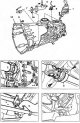
Removal and installation of manual transmission
Removal 1. Disconnect the negative cable from the battery. 2. Remove the gear shift lever 1 (figure 4.4). 3. Remove the engine protective cover. 4. Unscrew the bolts...
Removal 1. Disconnect the negative cable from the battery. 2. Remove the gear shift lever 1 (figure 4.4). 3. Remove the engine protective cover. 4. Unscrew the bolts...

Reverse light switch
The reversing light switch is shown in the figure 4.5. Figure 4.5. Reverse light switch: 1 - Reverse light switch; 2 - Thrust part.
The reversing light switch is shown in the figure 4.5. Figure 4.5. Reverse light switch: 1 - Reverse light switch; 2 - Thrust part.

Gearbox housing
Removal 1. Remove the gearbox. Disassembly 2. Remove the protective cover 8 (figure 4.6). 3. Remove finger 1. 4. Remove the lower part of the gear shift lever. 5....
Removal 1. Remove the gearbox. Disassembly 2. Remove the protective cover 8 (figure 4.6). 3. Remove finger 1. 4. Remove the lower part of the gear shift lever. 5....

Gearshift fork guide plate
Removal 1. Remove the gearbox. 2. Remove the lever 10 and bearing 11 of the clutch release (figure 4.9). 3. Loosen the mounting bolts 9 of the thrust plate 8. Unscrew...
Removal 1. Remove the gearbox. 2. Remove the lever 10 and bearing 11 of the clutch release (figure 4.9). 3. Loosen the mounting bolts 9 of the thrust plate 8. Unscrew...

Primary shaft — removal and installation
Removal 1. Remove the input shaft seal. 2. Remove the retaining ring 5 (figure 4.10). 3. Press out the primary shaft 7 in the direction of the retaining ring 8. 4....
Removal 1. Remove the input shaft seal. 2. Remove the retaining ring 5 (figure 4.10). 3. Press out the primary shaft 7 in the direction of the retaining ring 8. 4....

Gearbox cover
The gearbox cover is shown in the figure 4.11. Figure 4.11. Gearbox cover: 1 - Bolt; 2 - Guide plate; 3 - Retaining ring; 4 - Ball bearing; 5 - Outer ring of tapered...
The gearbox cover is shown in the figure 4.11. Figure 4.11. Gearbox cover: 1 - Bolt; 2 - Guide plate; 3 - Retaining ring; 4 - Ball bearing; 5 - Outer ring of tapered...

Secondary and intermediate shafts
Removal 1. Remove the gearbox. Disassembly 2. Disassemble the gearbox housing. 3. Remove the cone ring 6 and the inner ring 7 of the synchronizer (figure 4.19). Figure...
Removal 1. Remove the gearbox. Disassembly 2. Disassemble the gearbox housing. 3. Remove the cone ring 6 and the inner ring 7 of the synchronizer (figure 4.19). Figure...

Disassembly and assembly of the secondary shaft
The secondary shaft in disassembled condition is shown in the figure 4.20. Figure 4.20. Secondary shaft in disassembled state: 1, 12, 16, 30, 32, 42 - Needle bearings;...
The secondary shaft in disassembled condition is shown in the figure 4.20. Figure 4.20. Secondary shaft in disassembled state: 1, 12, 16, 30, 32, 42 - Needle bearings;...

Adjusting the axial clearance of the intermediate shaft
1. Disconnect the bearing cap 2 (figure 4.48). Figure 4.48. Disconnect bearing cover 2. 2. Remove the adjusting ring 3 (figure 4.49). Figure 4.49. Remove adjusting ring...
1. Disconnect the bearing cap 2 (figure 4.48). Figure 4.48. Disconnect bearing cover 2. 2. Remove the adjusting ring 3 (figure 4.49). Figure 4.49. Remove adjusting ring...

Gear shift lever
Removal 1. Remove the rubber accordion 1 from the lever 4 (figure 4.54). 2. Unscrew the mounting bolt 2 and remove the washer 3. 3. Pull lever 4 upwards. Installation 4....
Removal 1. Remove the rubber accordion 1 from the lever 4 (figure 4.54). 2. Unscrew the mounting bolt 2 and remove the washer 3. 3. Pull lever 4 upwards. Installation 4....

Lower part of the gear shift lever
Removal 1. Remove the gear shift lever. 2. Remove cover 1 (figure 4.55). 3. Remove cylindrical pin 3 using a punch with a diameter of 18 mm. 4. Remove the lower part of...
Removal 1. Remove the gear shift lever. 2. Remove cover 1 (figure 4.55). 3. Remove cylindrical pin 3 using a punch with a diameter of 18 mm. 4. Remove the lower part of...

Gear shift cylinder
Removal 1. Disconnect pipe 5 from cylinder 1 (figure 4.56). 2. Loosen plug 8 of the power take-off (PTO) switch (arrow) and remove it. 3. Remove cylinder 1. Installation...
Removal 1. Disconnect pipe 5 from cylinder 1 (figure 4.56). 2. Loosen plug 8 of the power take-off (PTO) switch (arrow) and remove it. 3. Remove cylinder 1. Installation...

Cardan transmission
The cardan transmission is shown in the figure 4.103. Figure 4.103. Cardan transmission: 1 - Nuts; 2 - Leading flange; 3 - Handle; 4 - Key; 5 - Cardan shaft; 6 - Rear...
The cardan transmission is shown in the figure 4.103. Figure 4.103. Cardan transmission: 1 - Nuts; 2 - Leading flange; 3 - Handle; 4 - Key; 5 - Cardan shaft; 6 - Rear...

Tightening torques for transmission components and parts
Tightening torques for transmission components and parts Fastening elements Tightening torques (Nm) Clutch Clutch housing to flywheel mounting bolts 25 Bolt for...
Tightening torques for transmission components and parts Fastening elements Tightening torques (Nm) Clutch Clutch housing to flywheel mounting bolts 25 Bolt for...
This section is available on: russian, bulgarian, belarusian, ukrainian, serbian, croatian, romanian, polish, slovak, hungarian
More similar sections for repairing other models
☛ Transmission: Transmission car Mercedes W168 (1997-2004)
☛ Transmission: Car gearbox car Mercedes W202 (1993-2000)
☛ Transmission: Mechanical gearbox car Mercedes W124 (1984-1995)
☛ Transmission: Mechanical gearbox car Mercedes W163 (1997-2005)
☛ Transmission: Car gearbox car Mercedes W116 (1972-1980, petrol)
Link in different formats to this section
TEXTHTMLBB Code
- General information
- Maintenance
- Power unit
- Engines 602.984/985
- Engines 904.908/914/923/936
- Transmission
- Clutch
- Manual gearbox 711.613
- Manual gearbox 710.64/66
- Manual gearbox 715.051
- Automatic gearbox 723.345
- Power take-off box
- Chassis
- Front suspension
- Rear suspension
- Steering
- Brake system
- Body and electrical equipment
- Interior (internal elements)
- Exterior (external elements)
- Heater and air conditioner
- Electrical diagrams
- General information
- User manual
- Maintenance
- Diesel engine OM646
- Engine repair
- Cooling and lubrication system
- Power and exhaust system
- Transmission
- Clutch
- Car gearbox
- Chassis
- Front suspension
- Rear suspension
- Steering
- Brake system
- Body
- Body elements
- Electrical equipment
- Equipment and devices
- Security systems
- Electrical circuits
- General information
- User manual
- Maintenance
- Petrol engines 2.0 l
- Engine repair
- Lubrication system
- Cooling system
- Power and control system
- Petrol engines 2.8 l
- Engine repair
- Lubrication system
- Cooling system
- Power and control system
- Diesel engines 2.3 l
- Engine repair
- Cooling system
- Lubrication system
- Turbocharging and recycling
- Power and control system
- Diesel engines 2.2 l
- Engine repair
- Cooling system
- Lubrication system
- Turbocharging and recycling
- Power and control system
- Transmission
- Clutch
- Mechanical gearbox
- Automatic gearbox
- Chassis
- Front suspension and wheels
- Rear suspension
- Steering
- Brake system
- Body
- Exterior (external elements)
- Interior (internal elements)
- Electrical equipment
- Equipment and devices
- Heater and air conditioner
- Electrical circuits
- General information
- Introduction to the guide
- Maintenance
- Power unit
- Engine repair
- Lubrication system
- Cooling system
- Power and exhaust system
- Transmission
- Clutch
- Mechanical gearbox
- Automatic gearbox
- Front axle
- Rear axle and cardan
- Chassis
- Car suspension
- Steering
- Brake system
- Tires and wheels
- Electrical equipment
- Equipment and devices
- Headlights and lighting
- Power devices
- Electrical circuits