
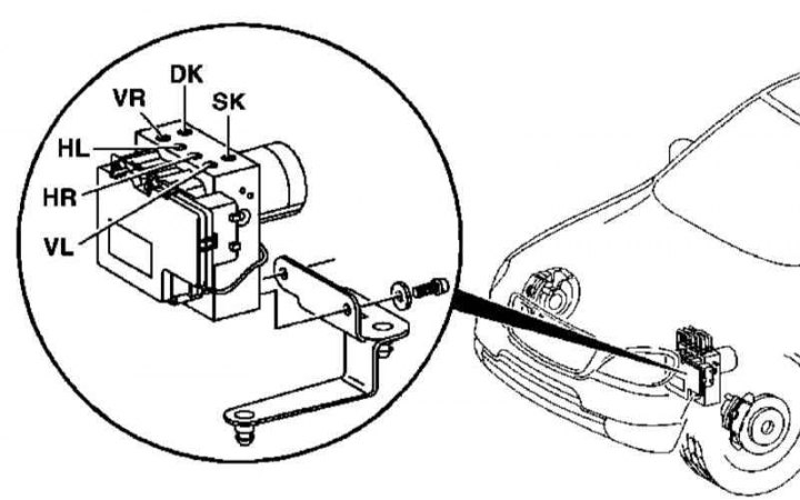
ETS/ESP hydraulic modulator installation details
DK - First working diagonal contour; HL - To the brake caliper of the left rear wheel; HR - To the brake caliper of the right rear wheel; SK - Second working diagonal contour; VL - To the brake caliper of the left front wheel; VR - To the brake caliper of the right front wheel
1. Details of the installation of the hydraulic modulator are shown in the illustration, to which all references in the text refer.
2. Turn off the ignition.
3. Remove the washer fluid reservoir (see chapter Body).
4. Having previously marked, disconnect the hydraulic lines from the ETS / ESP hydraulic modulator - immediately plug the open ends of the lines and union connectors.
5. Remove the left front wheel and wheel arch protection locker.
6. Release the bayonet lock and disconnect the hydraulic modulator 15-pin electrical connector.
7. Unbolt from the carrier plate, remove the hydraulic modulator and remove it from the engine compartment through the wheel arch, after releasing the ventilation line of the transfer case from the clamps. If necessary, lift up and remove the mounting plate from the rubber pads.
8. Installation is carried out in the reverse order - make sure that the hydraulic lines are connected correctly.
9. Finally, bleed the brake system (see Section Bleeding the brake system) and clear the memory of the on-board self-diagnosis module (see chapter Engine Electrical Systems).