
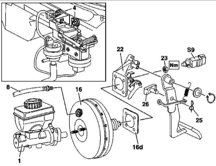
Brake booster installation details (on the example of models with AT, version 1)
S9 - Brake light switch (4 pin)
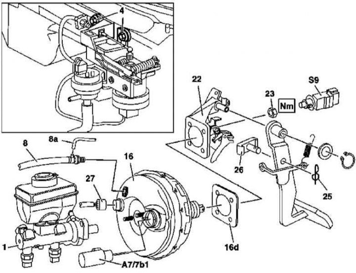
Brake booster installation details (on the example of models with AT, version 2)
Removal / installation of the brake booster
Removal / installation of the brake booster
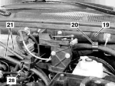
21 - Hoses
28 - Bracket
1. Illustrative material on the procedure for removing / installing the brake booster is presented in the illustrations, which include all references in the text.
2. Remove GTZ (1) (see Section Removal and installation of the main brake cylinder), - if there are signs of leaks from the rear side of the primary piston, the cylinder must be replaced.
3. Give nuts (4) position sensor mounts.
4. Disconnect the wiring harness from the diaphragm travel sensor BAS (А7/7b1).
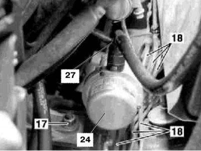
5. On diesel models, give the nut (17) on the left front powertrain mount and hang the left end of the engine.
6. On diesel models 163.113 (according to VIN 093126) remove the vacuum pump control module (24).
7. On diesel models, align the brake lines (18).
8. Give the plastic locknut (19), - try not to damage the plastic retainer (20).
9. Disconnect the wiring connector (27) BAS release switch.
10. Remove the cover on the left under the instrument panel.
11. Remove the retainer (25) and release your finger (26).
12. Give fixing nuts (23) and remove the brake booster (16) from pedal bracket (22), - take care not to damage the cylinder head cover.
13. Installation is in reverse order - do not forget to replace the seal (16d) and self-locking GTZ mounting nuts.
14. Finally, bleed the brake system (see Section Bleeding the brake system) and check that the brake light switch is working properly.
Diaphragm travel sensor BAS
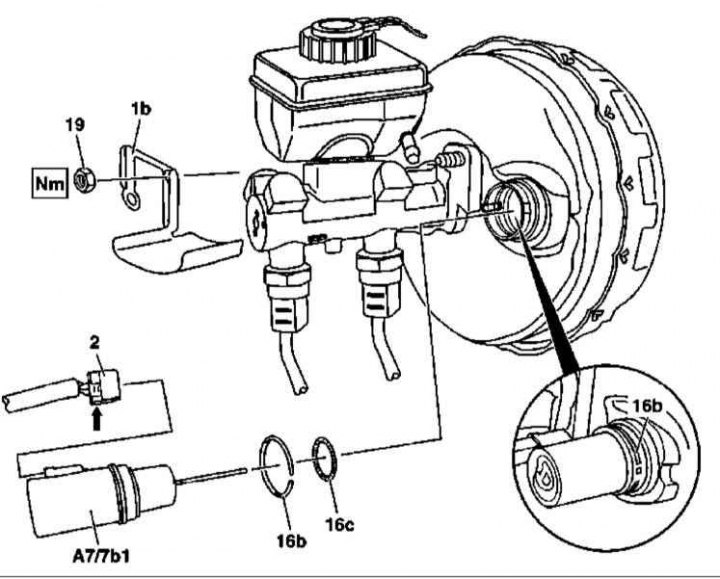
BAS Diaphragm Stroke Sensor Installation Details
1. The installation details of the BAS diaphragm travel sensor are shown in the illustration, to which all references in the text refer.
2. Depress the foot brake pedal several times to relieve the residual vacuum in the brake booster system (А7/7b1).
3. Giving the nut (19), remove the heat shield (1b) with GTS.
4. Squeezing out the latch tab located below (arrow), disconnect the connector (2) BAS Diaphragm Stroke Sensor Wiring.
5. Using a suitable tool, remove the circlip (16b).
6. Pull outward to remove the BAS Diaphragm Stroke Sensor from its seat (А7/7b1).
7. Check the condition of the O-ring (16s), replace if necessary.
8. Installation is carried out in the reverse order - make sure that the sensor is fully seated in the receiving socket.