
Removing
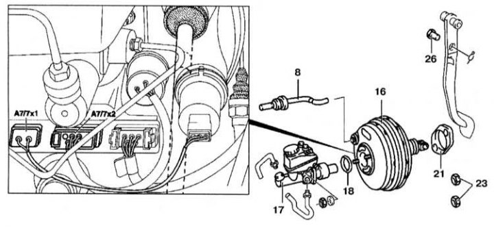
Installation details of the brake booster servo
1. Remove the brake master cylinder (see Section Dismantling and assembly of the main brake cylinder (GTZ) type «Tandem» (models 140.028/032/033/135)).
2. Remove the ASR support pump.
3. Check the GTZ for damage and leaks.
4. Unscrew or unhook the vacuum tube (8) from the vacuum booster (16). Press the brake pedal several times to reduce the pressure in the vacuum booster.
5. Disconnect the connector (A7/7x1), (A7/7x2) from the BAS control unit or on models with ESP, disconnect the connector from the solenoid valve switch and the BAS diaphragm displacement sensor on the vacuum booster. On models with BAS and ESP, the BAS control unit is integrated with the ESP control unit.
6. Remove the bottom cover of the panel of devices.
7. Disconnect the brake pedal return spring.
8. Remove the retainer and pin (26).
9. Loosen the nut (23) from bracket (22).
10. Remove the vacuum booster (16).
11. Check gasket (16).
Installation
Installation is carried out in the reverse order of removal.
Examination
1. Press the brake pedal to reduce the pressure in the vacuum booster.
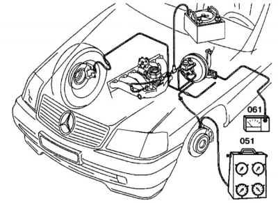
2. Disconnect the tester from the vacuum booster. 3. Connect pressure gauge (051) to the brake caliper with adapter.
4. Attach the pedal force sensor (06) to the brake pedal.
5. Start the engine and build up a pressure of 0.75 - 0.80 bar by depressing and releasing the accelerator pedal. If a vacuum is reached that is significantly lower than required, or the vacuum immediately decreases, then the sealing ring between the vacuum booster and the brake master cylinder is damaged, or the valve in the vacuum tube must be checked.
6. Apply the required force on the accelerator pedal and read the pressure in the line. The dependence of the pressure in the hydraulic drive on the force of pressing the foot brake pedal is given in Specifications.