



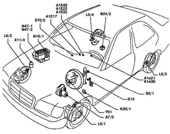
ASR/ETS traction control system component layout diagram
A1e17 - ABS malfunction indicator lamp; B24/2 - Lateral acceleration sensor (140.04/05/06/07); K20/1 - Pump relay; A7/3 - Hydraulic unit ASR/ETS; L6/1, L6/2 - Left and right front wheel speed sensors; L6/3, L6/4 - Left and right rear wheel speed sensors; N16/1 - Main control unit; S9/1 - Brake light switch; X11/4 - Diagnostic connector; Y61 - Master Cylinder Switching Valve
Only on models with ASR:
A1e21 - ASR warning light; A1e22 - ASR malfunction indicator lamp (models with BAS); A1e48 - BAS/ASR malfunction indicator lamp; N47-1 - ASR/SPS control unit; S76/5 - ASR switch.
Only on models with ETS:
A1e35 - ETS Malfunction Indicator Lamp; A1e36 - ETS signal lamp; N47-2 - ETS/SPS control unit