
Assembling the vacuum booster
Brake booster installation details (1 of 4)
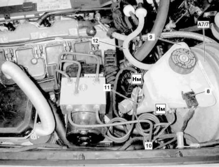
8 - Electrical wiring connector for the brake fluid level sensor; 9 - Brake fluid reservoir; 10 - Brake lines; 11 - GTZ; 12 - Vacuum line; A7/7 - Brake booster
Brake booster installation details (2 of 4)
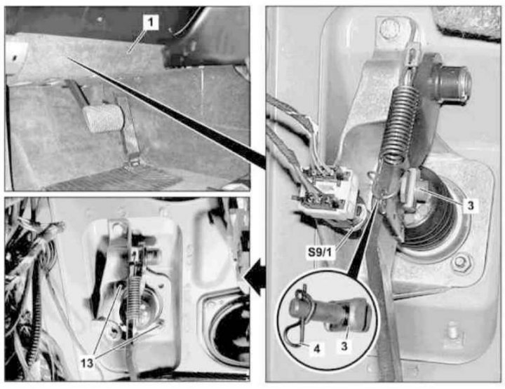
1 - Cover on the left under the instrument panel; 3 - Fixing bolt; 4 - Cotter pin; 13 - Nuts; S9/1 - Brake light switch
Brake booster installation details (3 of 4)
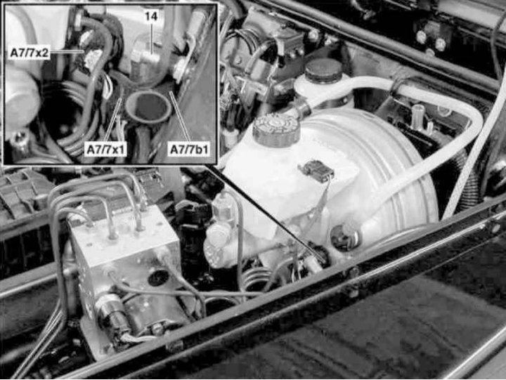
14 - Clamping bolt; 16b - Retaining ring; A7 / 7x1 - BAS diaphragm stroke sensor wiring connector; A7 / 7x2 - Connector for electrical wiring of the solenoid valve / sensor-switch release BAS; A7/7b1 - Diaphragm stroke sensor BAS
Brake booster installation details (4 out of 4)
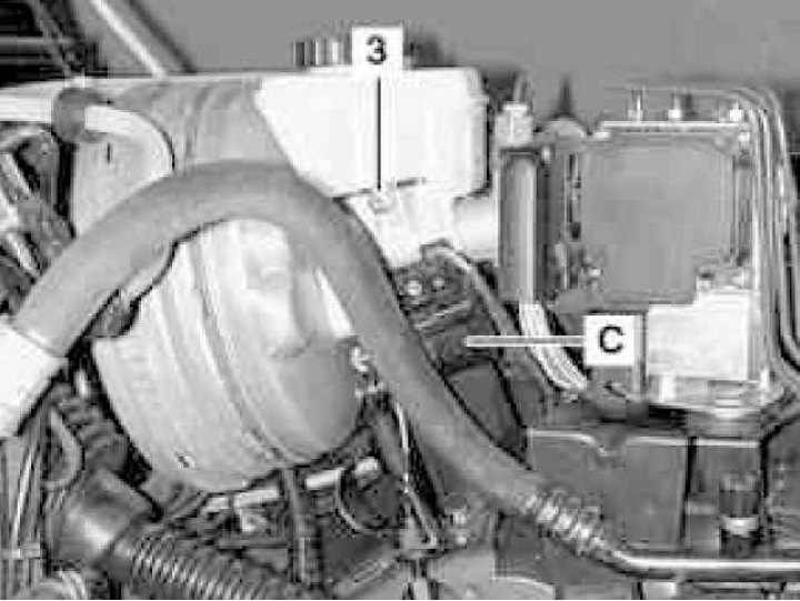
3 - Mounting bolt
C - Control unit
1. Disconnect the connector (8) wiring harness for brake fluid level sensor on reservoir (9) brake fluid.
2. Disconnect from GTZ (11) brake lines (10).
3. Disconnect the connector (A7/7x2) solenoid valve/sensor-switch release BAS wiring, as well as a connector (A7/7x1) diaphragm travel sensor BAS.
4. In order to expand the free space, unscrew the clamping bolt (14) ground terminals for starting the engine from an external power source.
5. After relieving the vacuum by depressing the foot brake pedal several times, disconnect from the brake booster (A7/7) vacuum line (12), - evaluate the condition of the rubber bushing fixing the line, if necessary, replace it.
6. To expand the free space, remove the control box (WITH) and take it aside without disconnecting any communication lines.
7. Remove cover (1) on the left under the instrument panel.
8. Turning to the left, pull and remove the brake light switch (S9/1).
9. Remove cotter pin (4) and remove the bolt (3) fastening the pusher to the foot brake pedal. Evaluate the condition of the bolt, if necessary, prepare a replacement element - the cotter pin must be replaced without fail.
10. Give nuts (13), - all self-locking fasteners must be replaced without fail.
11. Remove the brake booster (A7/7) assembled with GTS (11).
12. Installation is carried out in the reverse order - lubricate the seating surface of the assembly with sealant before installation.
13. Finally, bleed the brake system (see Section Bleeding the brake system), inspect its hydraulic path for signs of leak development and check the correct operation of the brake lights.
Diaphragm travel sensor BAS
1. The installation details of the BAS diaphragm stroke sensor are shown in the illustration. Details of the installation of the brake booster (3 of 4)
2. Depress the foot brake pedal several times to relieve the residual vacuum in the brake booster system to release the sensor sealing ring.
Note. If the O-ring becomes retracted into the amplifier assembly, the sensor should be replaced.
3. In order to expand the free space, unscrew the clamping bolt (14) ground terminals for starting the engine from an external power source.
4. Disconnect the connector (A7/7x1).
5. Using a suitable tool, remove the circlip (16b), - the ring must be replaced without fail.
6. Pull out the sensor (А7/7b1) from its nest.
7. Installation is carried out in the reverse order - make sure that the sealing and retaining rings fit correctly. Soak the front of the O-ring with soapy water before inserting the sensor into the O-ring.
8. Start the engine, depress the foot brake pedal several times, then turn off the ignition again and make sure that there are no signs of air being sucked through the sensor.