
General information
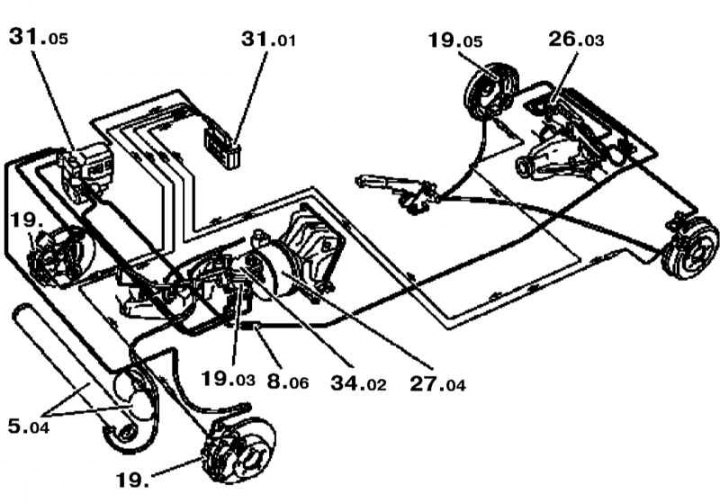
Scheme of the organization of the hydraulic drive of brake mechanisms for three-channel ABS
5.04 - Main and auxiliary vacuum receivers; 8.05 - Initial pressure valve; 19. - Fixed type calipers; 19.03 - GTZ; 19.05 - Rear wheel cylinders; 26.03 - Pressure regulator; 27.04 - Vacuum booster; 31.01 - Electronic control module; 31.05 - Hydromodulator; 34.02 - Brake fluid reservoir
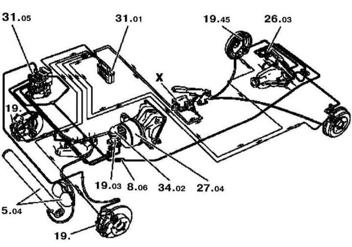
Scheme of the organization of the hydraulic drive of brake mechanisms for four-channel ABS
5.04 - Main and auxiliary vacuum receivers; 8.05 - Initial pressure valve; 19. - Fixed type calipers; 19.03 - GTZ; 19.05 - Rear wheel cylinders; 26.03 - Pressure regulator; 27.04 - Vacuum booster; 31.01 - Electronic control module; 31.05 - Hydromodulator; 34.02 - Brake fluid reservoir; X - Acceleration sensor
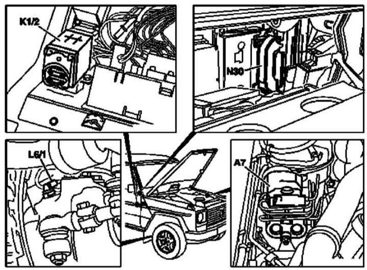
ABS/BAS/4-ETS/ESP Component Layout (1 of 4)
A7 - ABS hydraulic modulator; K1/2 - Overload protection relay (petrol models); K1/1 - Overload protection relay (diesel models); L6 / 2 - Right front wheel sensor; N30 - ABS control module
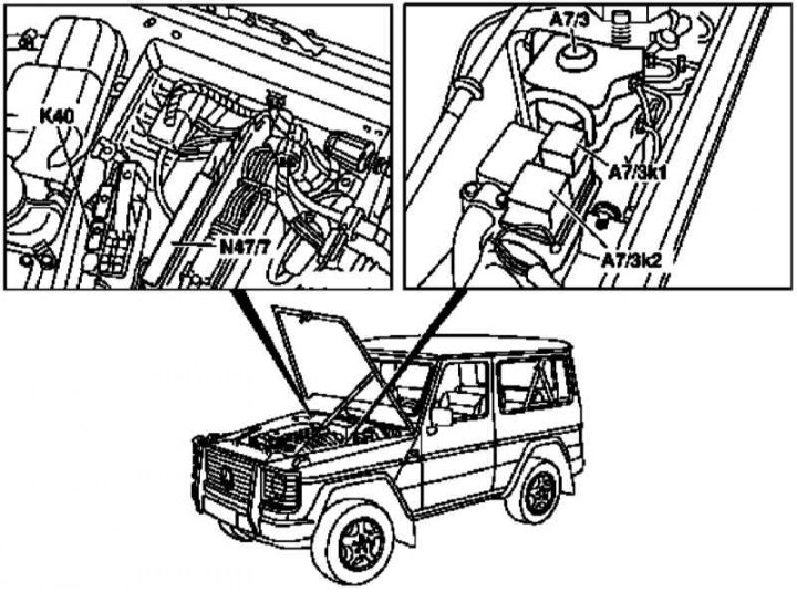
ABS/BAS/4-ETS/ESP Component Layout (2 of 4)
A7 / 3 - Hydromodulator ASR / ETS / ESP; A7 / 3k1 - Relay e / m valve; A7 / 3k2 - Pressure-return pump relay; K40 - Relay module (HFM-SFI, HFM-SFI with air pump, ME-SFI, EDC); N47/7 - ABS control module
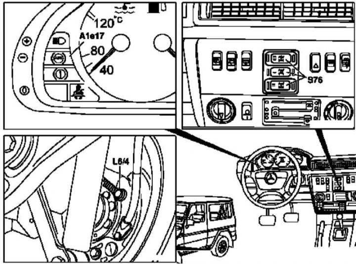
Component layout ABS/BAS/4-ETS/ESP, - three-channel ABS (3 of 4)
A1e17 - ABS warning lamp; L6 / 4 - VSS right rear axle; S76 - Differential lock switches
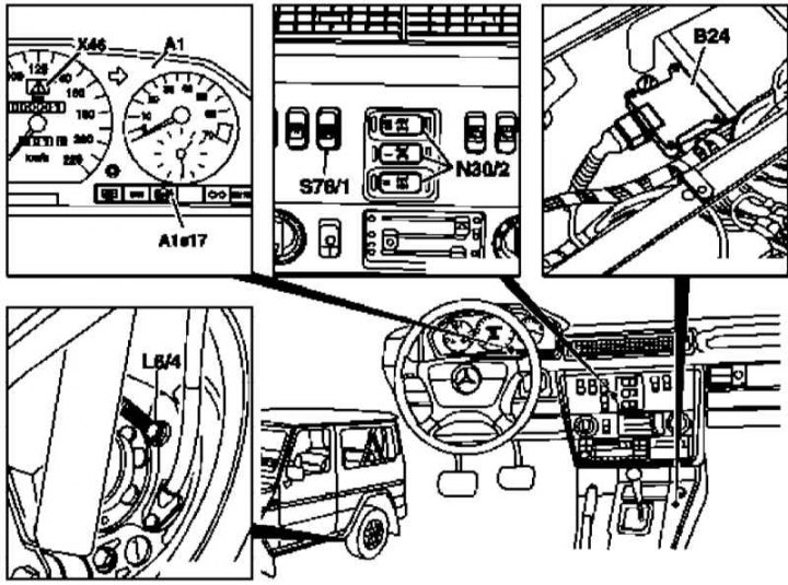
Component layout ABS/BAS/4-ETS/ESP, - 4-channel ABS (4 out of 4)
A1 - Instrument panel; A1e17 - ABS warning lamp; L6 / 3 - VSS left rear axle shaft (not shown); L6 / 4 - VSS right rear axle; X46 - Control lamp; S76/1 - ABS switch; N30/2 - ASD operation control switches; B24 - Acceleration sensor
The front and rear of all models covered in this manual are equipped with disc brakes with fixed type calipers in front and floating type in the rear.
The brake system consists of the main brake cylinder, vacuum booster and disc brakes of the front and rear wheels and is divided diagonally into two independent hydraulic circuits. If any of the circuits fails (e.g. as a result of seal failure) the second continues to function normally, providing adequate braking of the vehicle. Additionally, a pressure regulator valve is built into the circuits of both rear brake mechanisms, which provides dynamic adjustment of the braking force of the rear wheels in accordance with changes in the load on the rear axle of the car. Fluid pressure in both circuits is generated by a tandem brake master cylinder (GTZ). The GTZ is activated when the foot brake pedal is depressed.
Brief description of the principles of operation of auxiliary electronic systems of anti-lock brakes (ABS), emergency braking amplification (BAS), anti slip (4-ETS) and anti-skid (ESP) given in Part Operating techniques and auxiliary systems.
The brake fluid reservoir is attached to the brake master cylinder (GTZ) and supplies the entire hydraulic tract of the brake system with the working fluid.
On petrol models, the brake booster stores some of the vacuum created in the engine intake manifold. On diesel models, due to the absence of such a source of vacuum, a special vacuum pump is used. If necessary, a special valve ensures the connection of an appropriate source of vacuum, thereby providing an increase in the impact developed by the foot brake pedal.
The manual parking brake acts through cables on special shoe assemblies that are part of the rear wheel disc brakes.
Procedure for the operation of the ABS warning lamp while driving
1. Stop the car, turn off the engine and start it again.
2. Check the battery voltage level, if the measurement result is less than 10.5 V, recharge the battery.
Note. If the ABS warning lamp comes on at the beginning of the movement and then goes out after a while, this indicates a low battery voltage, which rises after the generator starts.
3. Make sure that the wire ends are securely fastened to the battery terminals, tighten the fasteners if necessary.
4. Jack up the car and place it on props, remove the wheels and check the condition of the wheel sensor wiring.
5. More detailed diagnostics should be carried out in a service station using special equipment to read fault codes stored in the memory of the control module (DTC).
Security measures
- Brake fluid is one of the highly toxic and chemically aggressive compounds and, in contact with body panels, destroys the paintwork!
- Brake dust generated during the wear of brake pads may contain asbestos, which is harmful to human health - in no case should you inhale it when cleaning the brake mechanisms!
- Working with the brake system requires special cleanliness and strict adherence to instructions. In the absence of the necessary experience, it is advisable to contact the service station.
Note. When driving on wet roads, periodically press the brake pedal to remove moisture from the brake discs.
- In the process of wheel rotation, moisture is discharged from the brake discs under the action of centrifugal force, but a silicone film, rubber abrasion products, grease and other contaminants that reduce braking efficiency remain!
- After installing new brake pads, the latter should run in - try to avoid sudden braking for the first 200 km after the replacement!
- Corroded disc brakes create a shaking effect during braking that does not disappear over time - replace the discs!
- Dirt sticking to the surface of the brake pads leads to the formation of grooves on the surface of the brake discs, which leads to a decrease in braking efficiency!