
Models 463.323 (M612)
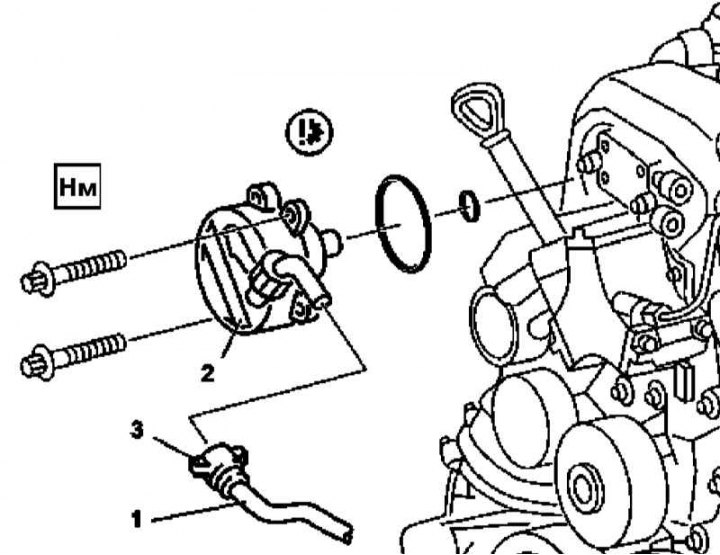
Vacuum pump installation details on models 463.323 (M612)
1 - Vacuum line; 2 - Vacuum pump; 3 - Retainer
1. Remove the viscous coupling of the cooling fan drive (see chapter Refrigeration, heating, ventilation and air conditioning systems).
2. Release the latch (3), disconnect from the pump (2) vacuum line (1).
3. Turn out fixing bolts and, having pulled forward, remove the vacuum pump (2).
4. Installation is carried out in the reverse order - make sure that the driver fits correctly on the back of the pump assembly, do not forget to replace the failed sealing elements.
Models 463.333 (M628)
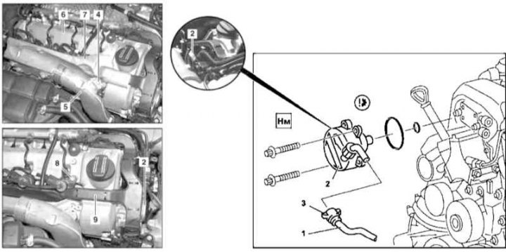
Vacuum pump installation details on models 463.333 (M628)
1 - Vacuum line; 2 - Vacuum pump; 3 - Retainer; 4, 8 - Bolts; 5 - Inlet air duct; 6 - Cylinder head cover; 7 - Cover; 9 - Cable box
1. Remove the air cleaner and air intake with integrated MAF sensor (see chapter Power supply and exhaust systems).
2. Release the right inlet air duct from the retainer on the body element.
3. Remove trim panel from oil filler neck.
4. Turn out a fixing bolt (4) and pull aside the air duct (5) on the cylinder head cover (6).
5. Remove the cover (7).
6. Turn out bolts (8) and remove from the guides on the cylinder head cover (6) cable box (9).
7. Jack up the car and put it on stands.
8. Remove the throttle actuator assembly with the upper air ducts (see chapter Power supply and exhaust systems).
9. Disconnect the guide tube of the dipstick for measuring the level of impellent oil.
10. Release the latches (3) and disconnect from the pump assembly (2) vacuum line (1).
11. Turn out fixing bolts and, having submitted forward, remove the vacuum pump (2).
12. Installation is carried out in the reverse order - make sure that the driver fits correctly on the back of the pump assembly, do not forget to replace the failed sealing elements.