
Front sensors
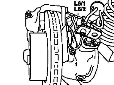
Installation details of the front ABS wheel sensor
L6 / 1 - Left front wheel sensor; L6 / 2 - Right front wheel sensor; 1 - Bolt
1. Remove the relevant front wheel.
2. Turn out a fixing bolt (1) and remove the sensor (L6/1 or L6/2).
3. Lightly lubricate its seat in the hub assembly, then disconnect the wiring from the sensor (X62/26 or X62/27).
4. Assess the condition of the rotor (measuring ring) on the hub assembly, replace if necessary (see Section Removal and installation of ABS wheel sensor rotors).
5. Installation is carried out in the reverse order.
Rear sensors
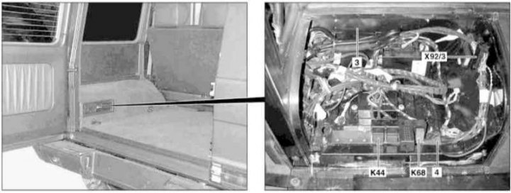
Wheel sensor wiring diagram
3 - Tool box in the luggage compartment
4 - wiring harness
X92 / 3 - ABS wiring connector
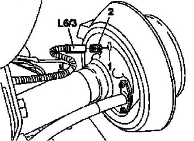
Installation details of rear ABS wheel sensor
1 - Bushing in the hub assembly
2 — Brass coupling
L6 / 3 - Wheel sensor
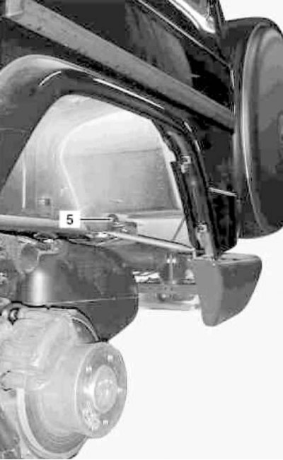
Port Location (5) in the floor panel
1. On models of the corresponding configuration (code ET2) activate the service mode of the TELE AID emergency call system (see Section Activation / deactivation of the service mode of the TELE AID emergency call system).
2. Turn on the auxiliary battery and connect it to the standard battery, then disconnect the negative cable from the latter.
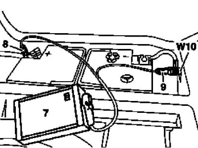
7 - Auxiliary battery
8 - Module positive wire terminal
9 - Terminal of the negative wire of the module
W10 - Battery Ground
3. Remove the appropriate rear wheel.
4. Carefully release the sensor (L6/3 or L6/4) made of brass bushing (1).
5. Assess the condition of the rotor (measuring ring) on the hub - if necessary, replace (see Section Removal and installation of ABS wheel sensor rotors).
6. Remove the brass sleeve (2).
7. Remove the relay mounting block in the engine compartment of the car (see chapter Onboard electrical equipment).
8. Disconnect the connector (Х92/3) ABS wiring harness routed in the toolbox (3) in the luggage compartment of the car.
9. Disconnect other harness connectors (4) inside the toolbox (3).
10. Remove the moisture shield.
11. Push the wiring harness (4) into the through hole (5) in the floor panel.
12. Disconnect from connector (Х92/3) wheel sensor wiring (L6/3 or L6/4) and finally remove the last assembly with the harness.
13. Installation is carried out in the reverse order - follow the correct wiring, to fix the harness, use a new insulating tape.
14. Appropriate models (code ET2) deactivate the service mode of the TELE AID system (see Section Activation / deactivation of the service mode of the TELE AID emergency call system).
15. 2 Finally, read the DTCs and clear the OBD memory using the STAR DIAGNOSIS scanner (6511 1801 00) (see chapter Engine Electrical Systems).