
ABS/EBV control module
For petrol models manufactured before 11/30/00.
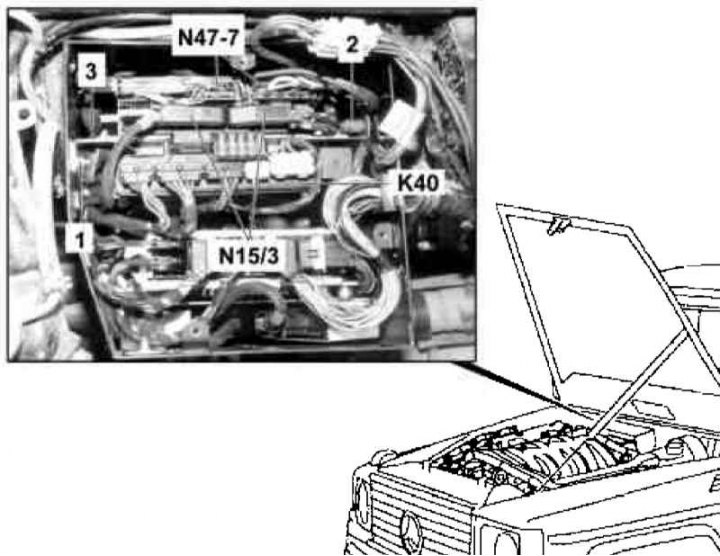
ABS/EBV Control Module Installation Details on Petrol Models after 11/30/00
1 - Nut; 2 - Rubber plugs; 3 - Holder; K40 - Relay module; N15/3 - ETC control module; N47-7 - ABS/EBV control module
1. Disconnect the negative cable from the battery.
2. Release the connector lock and disconnect the wiring from the ETC control module (N15/3).
3. Pulling up, remove and, without disconnecting the electrical wiring, set aside the relay module (K40).
4. Release the connector lock and disconnect the electrical wiring from the ABS/EBV control module (N47-7).
5. Loosen the nut (1) on the mounting plate.
6. Pull up to remove the holder (3).
7. Remove ABS/EBV control module (N47-7).
8. Installation is carried out in the reverse order - make sure that the holder fits correctly with respect to the rubber plugs (2), make sure that the wiring is not pinched.
9. In conclusion, clear the memory of the processor of the on-board self-diagnosis system (see chapter Engine Electrical Systems).
ABS control module
For models 453.250/333 manufactured before 09/30/01.
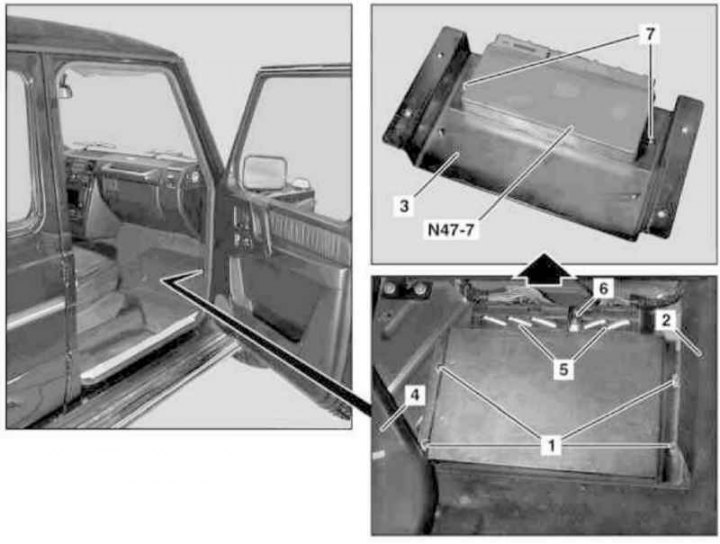
Details of installation of the ABS control module on models 463.250/333 of release on 30.09.01
1, 7 - Nuts; 2 - Panel in the passenger foot well; 3 - Mounting plate; 4 - Air supply hose to the right rear foot well; 5, 6 - Connectors; N47-7 - ABS/EBV control module
1. On models of the corresponding configuration (code ET2) activate the service mode of the TELE AID emergency call system (see Section Activation / deactivation of the service mode of the TELE AID emergency call system).
2. Turn on the auxiliary battery and connect it to the standard battery, then disconnect the negative cable from the latter.
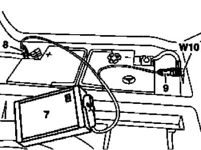
7 - Auxiliary battery
8 - Module positive wire terminal
9 - Terminal of the negative wire of the module
W10 - Battery Ground
3. Remove the floor carpet panel in the right front footwell.
4. Give nuts (1), - if necessary, lift the panel (2).
5. Raise the duct slightly (4) and with mounting plate (3) remove the ABS control module (N47-7).
6. After releasing the latches, disconnect the connectors (5).
7. Remove the connector (6).
8. Give nuts (7) and remove the control module (N47-7) from mounting plate (3).
9. Installation is carried out in the reverse order, - with the appropriate configuration (code ET2) deactivate the service mode of the TELE AID system (see Section Activation / deactivation of the service mode of the TELE AID emergency call system).
10. Finally, read the DTCs and clear the OBD memory using the STAR DIAGNOSIS scanner (6511 1801 00) (see chapter Engine Electrical Systems).
ESP/ABS/BAS control module
For models 463.246/249/323 and 463.250/333 from 09/30/01 y.
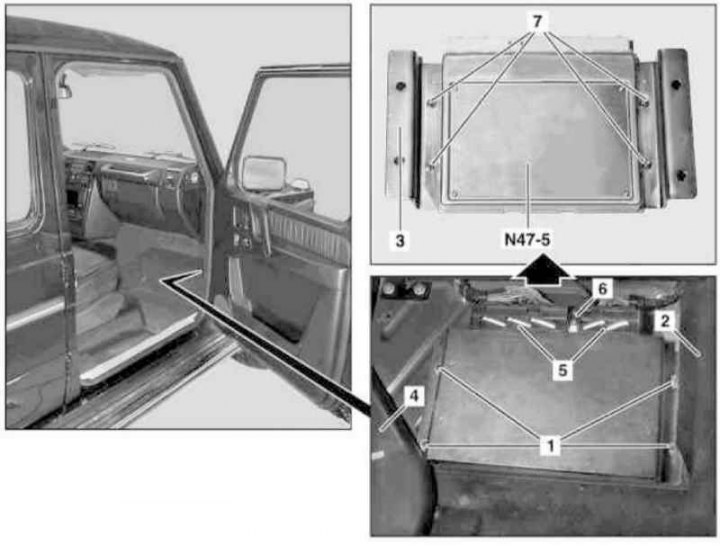
Installation details of the ESP control module on models 463.246/249/323 and 463.250/333 from 09/30/01 of issue.
1, 7 - Nuts; 2 - Panel in the passenger foot well; 3 - Mounting plate; 4 - Air supply hose to the right rear foot well; 5, 6 - Connectors; N47-5 - ESP/BAS control module
The procedure for performing the procedure is similar to that described in the previous subsection for the ABS module (N47-7). The ABS and BAS control modules are in this case integrated into the ESP module.