



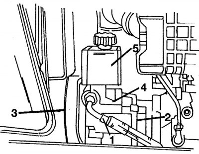
Figure 264. Location of the power steering pump and its reservoir on a diesel engine without turbocharging: 1 - flexible high pressure hose; 2 - return hose; 3 - pulley and drive belt; 4 — power steering pump; 5 — power steering reservoir
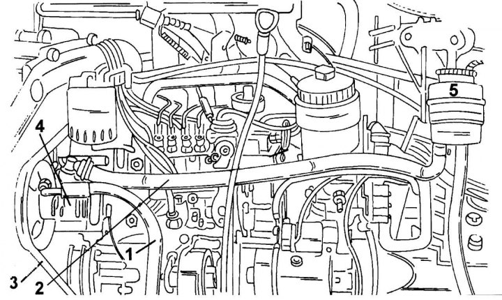
Figure 265. Location of the power steering pump and its reservoir on a turbocharged diesel engine: 1 - flexible high pressure hose; 2 - return hose; 3 - pulley and drive belt; 4 — power steering pump; 5 — power steering reservoir
The pump mount varies depending on the modification. Therefore, the following description should be compared with the recommendations for the installed engine type. Figure 264 shows the location of the pump on a non-turbocharged diesel engine. In Figure 265 the pump is shown on a turbocharged engine. To begin work, you need to free the front of the car. The power steering pump must be removed in the following order:
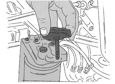
Figure 263. Checking the power steering fluid level
- unscrew the cap of the power steering reservoir (see figure 263) and pump out the fluid from the hydraulic drive system. At the same time, do not allow liquid to come into contact with painted parts of the car. The best way to pump out the liquid is with a rubber bulb, the tip of which is lowered into the tank;
- unscrew the union nut of the flexible hose 1 (see figure 264 and 265) high pressure. There is a sealing ring underneath it. When assembling, tighten the nut to a torque of 35–40 N·m;
- loosen the bolts securing pulley 3 of the power steering pump, holding the pulley from turning. On non-turbocharged petrol and diesel engines, first remove the air intake hose;
- remove the drive belt (see section "Cooling system") and take out the pulley;
- unscrew pump 4. Remove it and drain any remaining liquid inside.
Original source of information mercedesman.ru
Assembly is carried out in reverse order. Tighten the pump mounting bolts to 21 N·m, and the pulley bolts to 30 N·m. After completing the assembly, fill the system with fluid as described above and bleed.