
Conventional Steering Pump
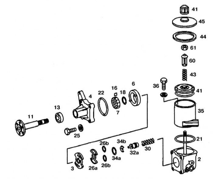
Conventional Steering Pump Design
2 - Pump casing; 3 - Plate; 4 - Flange; 6 - Cam insert; 7 - Rotor; 11 - Drive shaft; 13 - Oil seal; 16 - Blade; 18, 34a, 34b - Retaining rings; 21, 22, 26a, 26b, 44 - O-rings; 30, 43 - Springs; 32 - Flow control valve; 35 - Reservoir; 36 - Bolt; 41 - Filter; 45 - Cover; 47 - Ventilation cover; 60 - Plastic sleeve; 61 - Nut
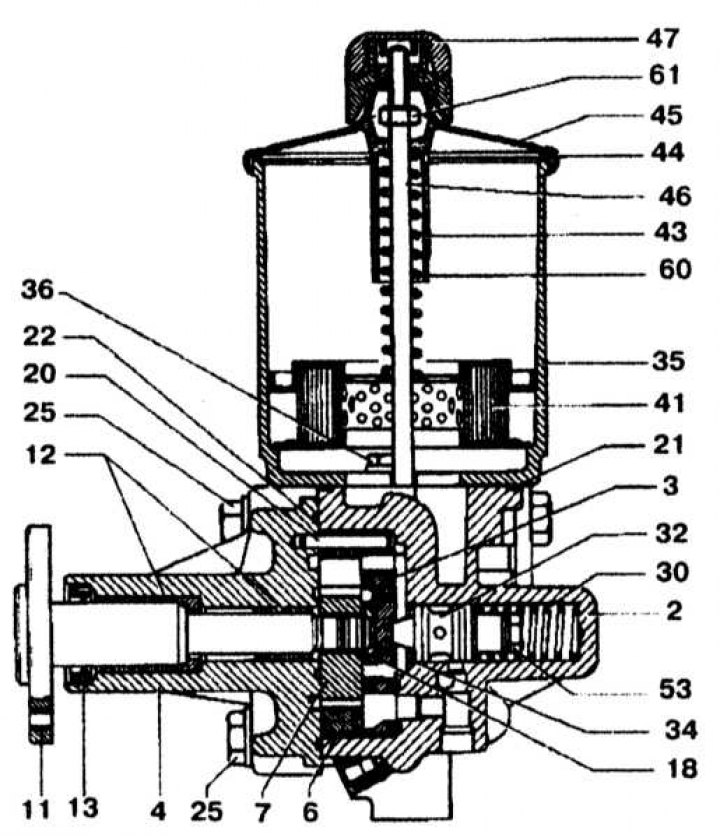
Conventional Steering Pump Design
Disassembly
1. Unscrew the ventilation cap (47) and remove the cover (45).
2. Loosen the nut (61) from the support bolt, remove the plastic sleeve (60), spring (43) and filter (41).
3. On Vickers/LUK pumps, reservoir (35) can be removed, replace the O-ring. On ZF pumps, the reservoir is molded together with the casing (2).

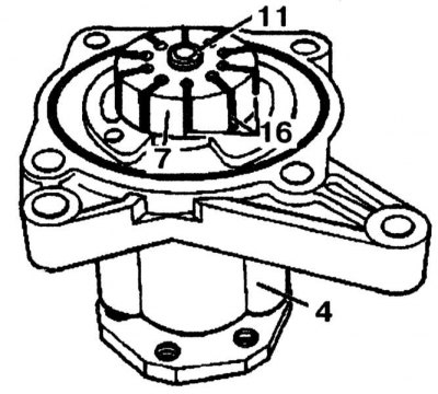
4. Remove the bolts (25) and remove the flange (4). Check the bottom of the flange (4) for damage and wear.

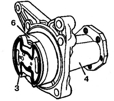
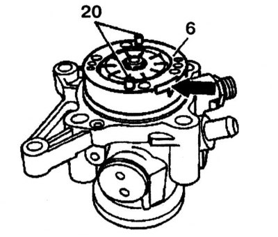
5. Remove pressure plate (3) and cam insert (6).
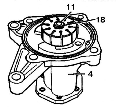
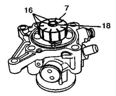
6. Remove retaining ring (18) from the drive shaft (11).Replace the circlip.
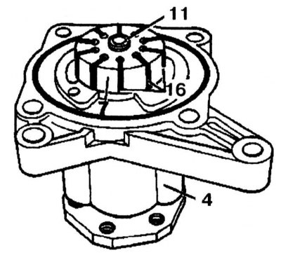
7. Remove the rotor (7) using plastic hammer with drive shaft (11) along with blades (16) (10 pieces).
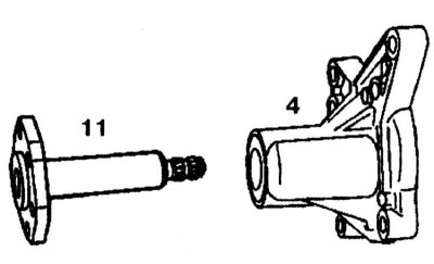
8. Remove the drive shaft (11) from the flange (4).
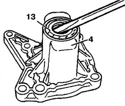
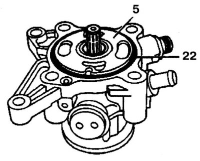
9. Using a screwdriver, press out the radial oil seal (13) from the flange (4).
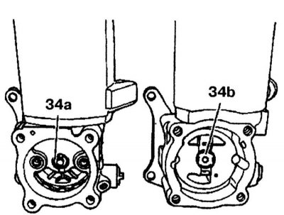
10. Remove retaining ring (34a) or (34b).
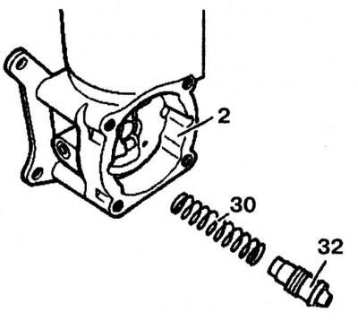
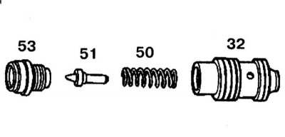
11. Remove fluid flow control valve (32) and spring (30) from the pump housing (2).

12. Attach the fluid flow control valve (32) in a vise and unscrew the valve (53) from the overpressure valve.
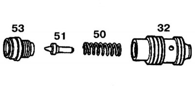
13. Remove the sealing cone (51) and spring (50), check the contact surfaces of the fluid flow control valve (32) and the opening in the pump housing for wear or damage. If wear on the sealing surfaces is determined, the pump must be replaced.
14. Check both sealing cones. Replace worn cone.
Assembly
1. Lubricate all parts with oil before starting assembly. Replace all o-rings. If a new valve is installed, fluid flow adjustment (32), pay attention to the correct opening pressure of the overpressure valve.
2. Assemble the fluid flow control valve (32), fixing it in a vise, and tighten the valve (53).

3. Insert the spring (30) and fluid flow control valve (32) into the pump housing (2).
4. Install retaining ring (34a) or (34b).

34a - Vickers/LUK pump
35b - ZF pump
5. Install a new oil seal into the flange using a punch.
6. Further installation is carried out in the reverse order of removal.
7. After assembling the pump, check that the pump is working properly and that there are no fluid leaks. If necessary, check the operating pressure of the pump.
Power steering pump type «Tandem» - models 62, 162
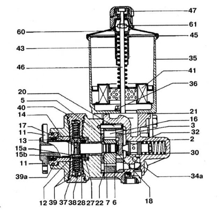
Steering pump design type «Tandem» (models 62, 162)
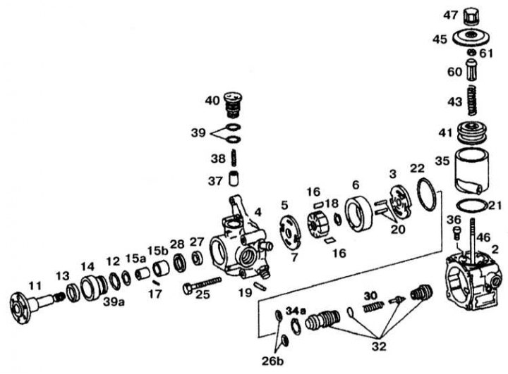
2 - Pump casing; 3 - Pressure plate; 4, 14 - Flanges; 5, 12 - Thrust washers; 6 - Cam insert; 7 - Rotor; 11 - Drive shaft; 13, 27 - Radial oil seals; 15a - Eccentric; 15b - Sleeve; 16 - Blade; 17, 19, 20 - Fingers; 18 - Retaining ring; 21, 22, 26b, 39, 39a - O-rings; 25, 36 - Bolts; 27 - Oil seal; 28 - Gasket; 30, 38, 43 - Springs; 32 - Fluid flow control valve; 35 - Reservoir; 37 - Piston; 40 - Screw cartridge; 41 - Filter; 45 - Cover; 46 - Support bolt; 47 - Ventilation cover; 60 - Plastic sleeve; 61 - Nut
Steering pump design type «Tandem» (models 62, 162) (2 of 2)
Disassembly
1. Unscrew the ventilation cap (47) and remove the cover (45).
2. Loosen the nut (61) support bolt (46). Remove the plastic sleeve (60), spring (43) and filter (41).
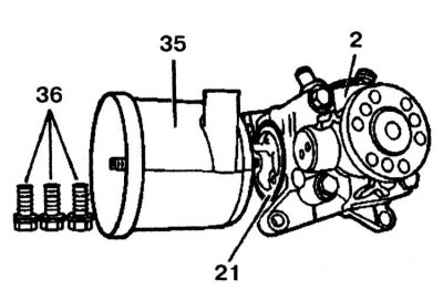
3. Remove the bolts (36) pump housing (2), remove the reservoir (35) and sealing ring (21).
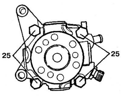
4. Remove the bolts (25) and remove the flange. Check the flange contact surface for wear and damage.
5. Remove pressure plate (3).
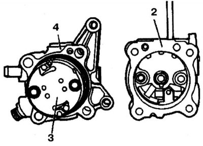
6. Remove the cam insert (6), check the contact surface of the pressure plate as well as the sliding surfaces of the vanes on the cam insert (6) for wear and tear.
7. Remove retaining ring (18) from the drive shaft. Replace retaining ring.
8. Remove the rotor (7) from the drive shaft (11) with a plastic mallet and remove the blades (16) (10 pieces), check the blades (16) in the grooves of the rotor (7), - they should slide in the rotor easily.
9. Remove thrust washer (5). On pumps of the type «Tandem» first version, gasket (5) was not installed. If the drive shaft on such a pump does not rotate easily, is seized or cracked, the pump must be replaced.
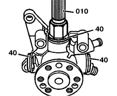
10. Remove all four cartridges (40) from the pump housing with a key (010).
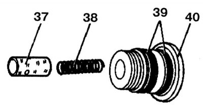
11. Check the seals (39) and replace them, if necessary, remove the piston (37) and spring (38) from the cartridge (40). Check piston and piston guide for signs of wear and damage. If the piston moves in the guide with noticeable difficulty, the cartridge must be replaced.
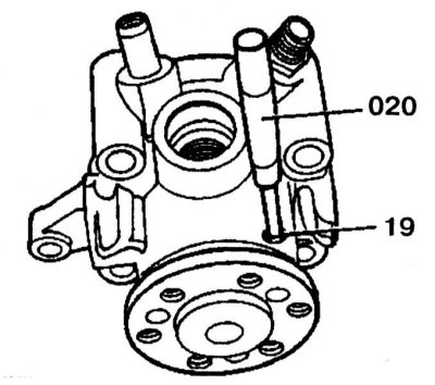
12. Knock out your finger (19) from the pump housing with a punch.
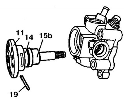
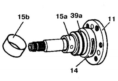
13. Remove the drive shaft (11) along with bushing (15b) and flange (14) from the pump housing.
14. Remove bushing (15b) and check it out.
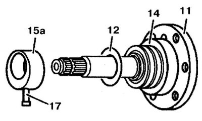
15. Knock out your finger (17) using a drift and remove the eccentric (15a), remove the thrust washer (12) and check its condition, remove the flange (14) from the drive shaft (11).
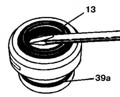
16. Using a screwdriver, remove the radial oil seal (13) from the flange, replace the O-ring (39a).
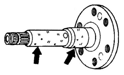
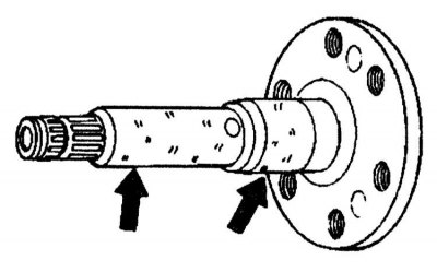
17. Check bearing surfaces (arrows) on the drive shaft for wear or nicks.
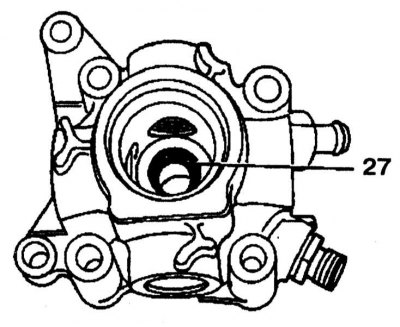
18. Check the radial oil seal (27) in the pump casing, if fluid is found on the pump, a leaking stuffing box is likely to be the cause (27).
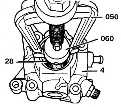
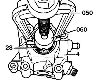
19. Remove the radial oil seal and gasket (28) using a puller, check the bronze bushing in the housing (4) for signs of wear and damage and, if necessary, replace it.
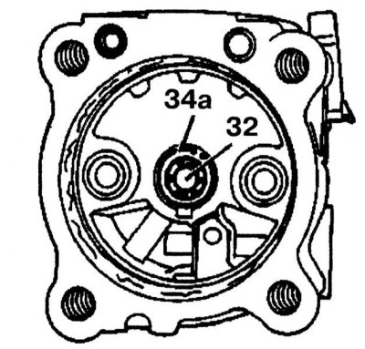
20. Remove retaining ring (34a). When removing the retaining ring, make sure that the pump housing is not damaged.
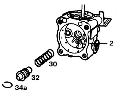
21. Remove fluid flow control valve (32) and spring (30) from the pump housing (2).
22. Attach the fluid flow control valve (32) in a vise and unscrew the valve (53) from the overpressure valve.
23. Remove the sealing cone (51) and spring (50), check the contact surfaces of the fluid flow control valve (32) and the opening in the pump housing for wear or damage. If wear on the sealing surfaces is determined, the pump must be replaced.
24. Check both sealing cones. Replace worn cone.
Assembly
1. Assembly is carried out in the reverse order of removal.
2. After assembling the pump, check that the pump is working properly and that there are no fluid leaks. If necessary, check the operating pressure of the pump.
Steering pump type «Tandem» - models 67, 167
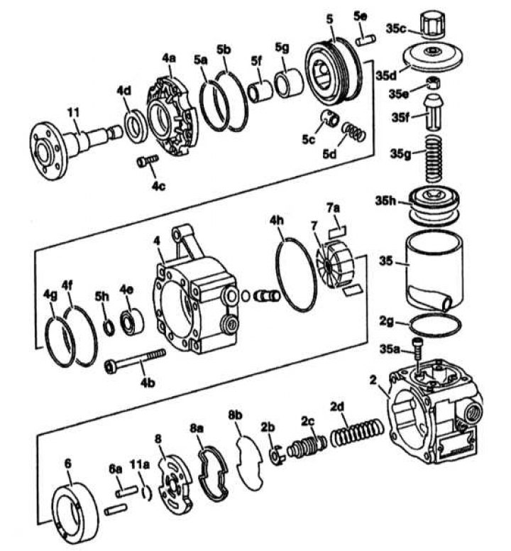
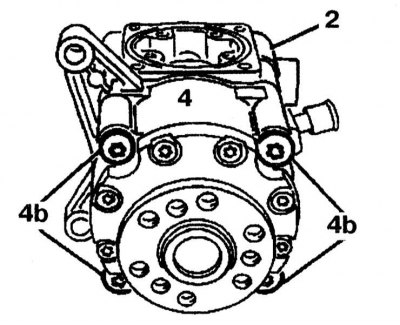
Power steering pump type «Tandem» - models 67, 167
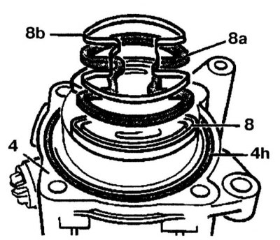
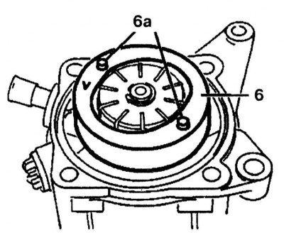
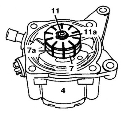
2 - Pump body; 2b, 2c - Fluid flow control valve; 2d, 5d, 35g - Springs; 2g, 4f, 4h, 5a, 5b, 35a - O-rings; 4 - Pump body; 4a - Flange cover; 4b, 4c - Bolts; 4d, 4e - Radial seals; 5 - Piston support ring; 5c - Piston; 5f - Sleeve; 5g - Bearing; 6 - Cam insert; 6a - Fingers; 7 - Rotor; 7a - Blades; 8 - Pressure plate; 8a - Oil seal; 8b - Gasket; 11 - Drive shaft; 11a - Retaining ring; 35 - Reservoir; 35c - Ventilation cover; 35d - Cover; 35e - Nut; 35f - Plastic sleeve; 35g - Spring; 35h - Filter
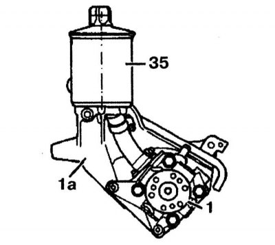
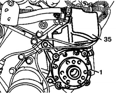
On models 140.04/050/051 tank (35) mounted on a bracket (1a), which in turn is screwed to the pump (1).
Remove the sealing cone (51) and spring (50). Attention: On models 140.04/050/051 the reservoir (35) mounted on a bracket (1a), which in turn is screwed to the pump (1).
Disassembly
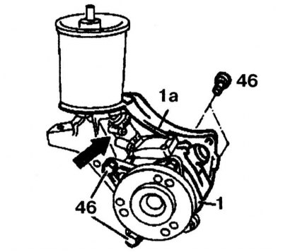
1. Loosen the clamp, disconnect the tube (arrow) and fix it on the side, unscrew the bolts (46) and remove the pump (1) from bracket (1a).
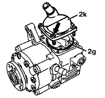
2. Remove the bolts (4 pieces), remove the cover (2k), check the o-ring (2g), replace it if necessary.
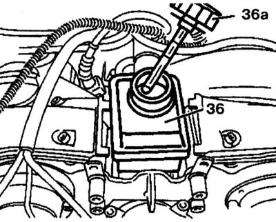
3. On models 140.056/057, on engine 120 pump (1) there is an expansion tank to adjust the oil in the tank (35), located between the thermostat and the intake manifold.
4. Oil level gauge (36a) with labels «MIN» And «MAX» for checking the oil level is located on the cover of the expansion tank (36).
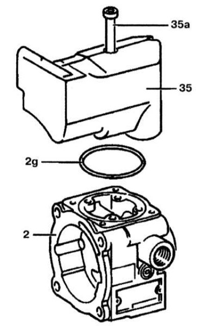
5. Remove four bolts (35a) tank mounts (35) and remove it, check the o-ring (2g), replace it if necessary.
6. Unscrew the ventilation cap (35c) and remove the cover (35d).
7. Loosen the nut (35e) with support bolt (35i). Remove the plastic sleeve (35f), spring (35g) and filter (35h).

8. Remove the bolts (4b) on the flange (4) and remove the pump housing (2).
9. Remove the O-ring (4h) from the flange (4), check and replace it, if necessary, remove the pressure plate (8), check the seal (8a) and cone gasket (8b) and replace the seal if necessary.
10. Remove the cam insert (6) and fingers (6a). Check the pressure plate surface as well as the vane sliding surface on the cam insert for wear or damage.
11. Remove retaining ring (11a) from the drive shaft (11). Replace retaining ring.
12. Remove the rotor (7) from the drive shaft (11) with a plastic mallet and remove all blades (7a) (10 pieces).
13. On the ZF pump, remove the drive shaft (11) from the flange (4). On Vickers/LUK pumps: first remove the 10 vanes and then remove the drive shaft with flange cover.
14. Check the drive shaft for nicks and wear on the bearing surfaces. If necessary, replace it.
15. Remove the bolts (4c) (8 pieces) and remove the flange cover (4a), check the radial oil seal (4d) and replace it if necessary.
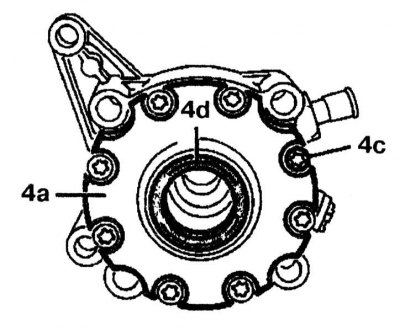
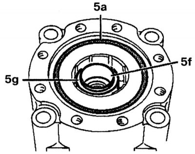
16. Replace O-ring (5a). On the ZF pump, remove the sleeve (5f) and bearing (5g). On Vickers/LUK pumps: Remove retaining ring from drive shaft, remove gasket and bushing (5f) with bearing (5g).
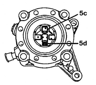
17. Remove the piston (5c) and spring (5d). Check piston and spring for wear and damage.
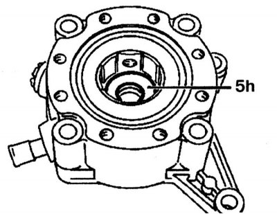
18. Remove gasket (5h) from the ZF pump housing.
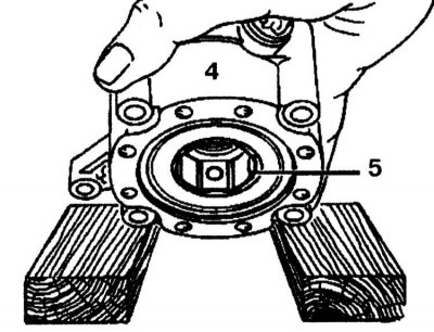
19. Fix the flange (4) between two wooden blocks so that the ring can be removed (5).
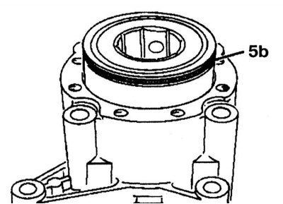
20. Replace O-ring (5b).
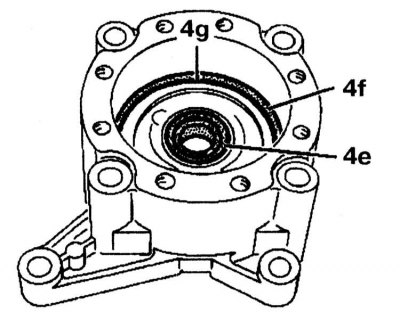
21. Replace O-ring (4f) and taper ring (4g) in the pump housing, check the radial seal (4e) and replace it if necessary.
22. Remove the radial oil seal (4e) using a puller, check the bronze bushing in the housing (4) for damage or wear and replace if necessary.
23. Remove fluid flow control valve (2c) and spring (2j) from the pump housing (2).
24. Attach the fluid flow control valve (2c) in a vise and unscrew the valve (2e) from the overpressure valve.
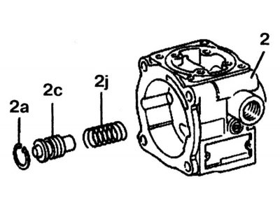
25. Remove the sealing cone (2f) and spring (2d). Check the contact surfaces of the fluid flow control valve (2c) and the opening in the pump housing for wear or damage. If wear on the sealing surfaces is determined, the pump must be replaced.
26. Check both sealing cones. Replace worn cone.
Assembly
Assembly is carried out in the reverse order of removal.
After assembling the pump, check that it is working properly and that there is no leakage of fluid. If necessary, check the operating pressure of the pump.