
General information
The design and principle of operation of a speed-sensitive hydraulic power steering mechanism are shown in Ref. illustrations.
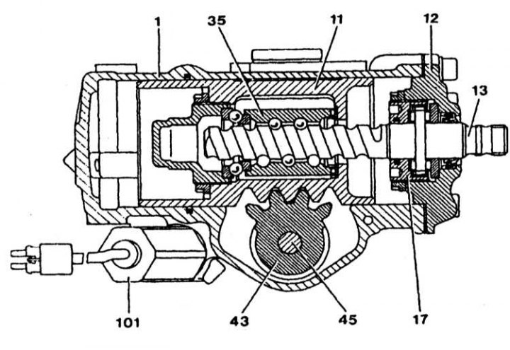
Steering gear design
1 - Steering gear housing; 11 - Piston; 12 - Upper bearing housing; 13 - Worm; 14 - Insert; 35 - Nut; 43 - Bipod shaft; 45 - Adjusting screw; 101 - Dosing valve
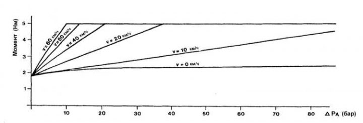
The principle of operation of the vehicle speed-sensitive power steering system
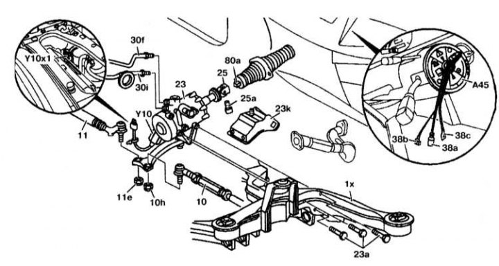
Removing

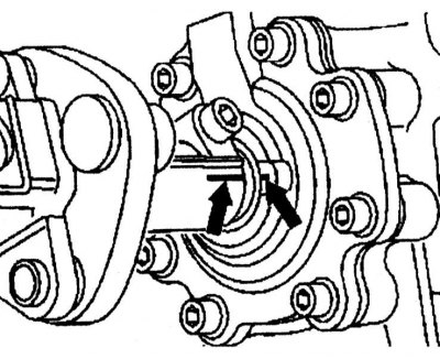
Steering Gear Installation Details
1. Install the steering column in the extended position.
2. Remove the fluid from the power steering reservoir.
3. Disconnect the P-valve (Y10x1) on the left side and disconnect the wiring connector from the steering gear.
4. Disconnect the tie rod (10) from the steering knuckle.
5. Disconnect the tie rod (11) from the steering knuckle.
6. Remove heat shield (23k).
7. Unscrew the return (30f) and forcing (30i) pipelines.
8. Remove the steering shaft lock. The steering wheel must not be able to rotate, otherwise the contact spring (A45) may be damaged after replacement.
9. Disconnect the steering shaft (80a) from the steering shaft (25).
10. Remove the bolts (23a) and remove the steering gear (23).
Installation
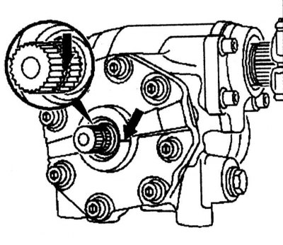
Steering Gear Installation Details
1. Set the steering gear to the middle position.
 |  |
2. Install the steering gear and screw it to the support on the front beam (1x).
3. Screw return (30f) and forcing (30i) pipelines.
4. Install the heat shield (23k).
5. Further installation is carried out in the reverse order of removal.
6. Fill fluid into power steering reservoir and check operation and leaks.