



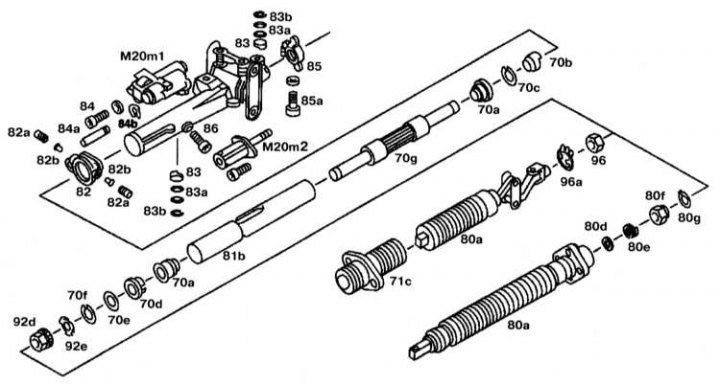
Electronically adjustable steering column design
Disassembly
1. Remove the steering column.
2. Remove the oil seal (71c) from the bottom of the steering shaft.
3. Disconnect the lower steering shaft (80a).
Examination
1. Check the lateral runout of the lower steering shaft (80a).
2. Remove the lower bracket (82).
3. Set the height adjuster to the middle position.
4. Remove the steering column tilt adjustment drive (up/down) (M20m²).
5. Remove the telescopic adjustment drive (inside/outside) (M20m1).
6. Remove the steering column stop (83).
7. Remove the bracket (85).
8. Loosen the cover mounting bolt (86) and remove the inner pipe downwards from the outer pipe.
9. Disassemble the inner tube.
Assembly
1. Assemble the inner tube.
2. Lubricate the inner tube (81b) and insert it from below into the outer tube.
3. Screw the bolt (86) into the guide, aligning the groove on the inner tube (81b) with the bolt.
4. Install the telescopic adjustment drive (inside/outside) (M20m1).
5. Further assembly is carried out in the reverse order of removal. The maximum permissible runout of the lower steering shaft is 2.0 mm.