
Release models before April 1984
Removing
Note: A new rubber steering collar clamp bolt will be required for installation.
1. Remove a decorative overlay from below from the panel of devices from the driver's side.
2. Remove the steering wheel as described in paragraph 17.
3. Following the description in Chapter 12, do the following:
- A) Remove the instrument panel from the instrument panel.
- b) Remove the switch block from the steering column.
4. Raise the front of the vehicle and place it on stands.
5. Working from below at the front of the vehicle where the base of the steering column connects to the steering gear, loosen and remove the top two bolts (see fig. 18.5). This will allow, when disconnecting the steering column, not to disconnect the clutch from the steering mechanism.
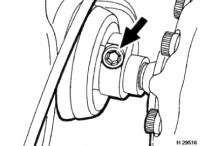
Pic. 18.5. Loosen and remove the top of the two bolts (shown by arrow) with elastic rubber sleeve
6. Turn away fastenings and remove a casing of a steering column.
7. Refer to paragraph 19 and remove the ignition switch/steering wheel lock assembly.
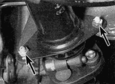
8. Turn away two nuts and take out bolts which fasten the top end of a steering column to a crossbar of fastening (see fig. 18.8).
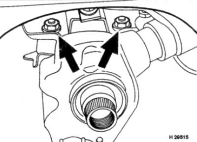
Pic. 18.8. Loosen the nuts and bolts on the top of the steering column (shown by arrows)
9. Loosen and remove the bolt that secures the lower section of the steering column to the bracket (see fig. 18.9). Make sure the threaded washer is fully seated on the bracket.
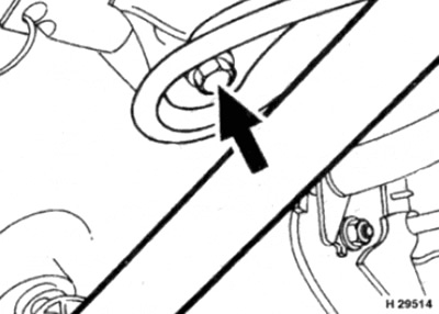
Pic. 18.9. Loosen and remove the lower steering column bolt (shown by arrow)
10. Pry the rubber guide bushing out of the hole in the bulkhead of the engine compartment. Remove the steering column from the vehicle.
Installation
11. Before installing the steering column, the steering gear should be centered, with the wheels positioned in the direction of rectilinear movement. To do this, unscrew the hex head plug on the steering gear (next to the steering column) (see fig. 18.11). Slowly turn the steering mechanism by the axis of the steering mechanism, observing the hole open after unscrewing the plug. The steering gear is centered correctly when the top of the piston (becomes visible through the hole) centering hole appears. It is best to fix the steering gear in this position with a long bolt, with a pointed end. It will engage with the piston and maintain steering adjustment when installed.
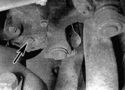
Pic. 18.11. Loosen the hex cap on the steering gear
12. Lubricate the O-ring on the base of the steering column lower shaft, then position the steering column and guide rubber bushing on the vehicle.
13. Insert and tighten by hand the upper and lower support bolts; don't overtighten them.
14. Install the ignition switch/steering wheel lock assembly as described in paragraph 19.
15. Align the base of the column with the flexible rubber sleeve on top of the steering gear. Insert a new draw bolt, but do not tighten it too much.
16. Tighten bolts of the top and bottom support of a steering column with the demanded effort.
17. Torque tighten the flexible coupling pinch bolt.
18. Turn out a fixing bolt (if you use) from the steering gear and tighten the hex head plug. After that, you can lower the car to the ground.
19. Establish the block of switches of a steering column and a casing.
20. Press the rubber guide bushing into the hole in the bulkhead of the engine compartment.
21. Install the instrument panel as described in Chapter 12.
22. Install the steering wheel as described in paragraph 17.
23. Establish a decorative slip on the lower part of the panel of devices.
Release models after April 1984
Removing
Note: A new steering column rubber collar clamp bolt will be required for installation.
24. Disconnect the negative battery terminal.
25. Remove the steering wheel as described in paragraph 17.
26. Remove the steering column lock as described in paragraph 19.
27. Remove the block of switches of the instrument panel and steering column, as described in Chapter 12 and remove the steering column cover.
28. Working in the engine compartment, using paint or marker, apply matching marks between the lower end of the steering column and the rubber sleeve. Note that on some models the steering gear heat shields must be unscrewed to gain access to the clutch.
29. Loosen and remove the top clutch pinch bolt securing the clutch to the steering column (see fig. 18.29).
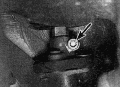
Pic. 18.29. Loosen and remove the upper rubber coupling pinch bolt
30. Loosen and remove the upper steering column mounting bolts (which are accessible through the opening of the instrument panel) and lower mounting nuts (see fig. 18.30, a, b).
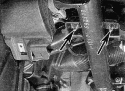
Pic. 18.30, in. Loosen the top steering column bolts (shown by arrows), which can be reached through the opening of the instrument panel...
Pic. 18.30 b....and lower mounting nuts
31. Remove the steering column cover sleeve from the engine compartment and remove the column from the vehicle. When the column is removed, check the condition of the rubber coupling, and if necessary, replace it (see paragraph 20).
Examination
32. The steering column is folding. In the event of a frontal collision, the shaft folds in and thus prevents the driver from being injured by the steering wheel. Before installing the column, check for damage or deformation of the column or supports. If found, replace.
33. Check the play of the shaft in the column bushings. If wear is found on the steering column bushings, the column should be repaired. Dispenser repair is a complex job that requires special tools, so it must be carried out at service stations.
Installation
34. Apply multi-purpose grease to the lower column bushing prior to installation.
35. Aligning the marks made before removal, install the column in place and insert it into the slots of the rubber sleeve.
36. Make sure that the column boot bushing is correctly positioned in the bulkhead, then install the nuts and bolts of the steering column, tightening them to the required force.
37. Fit a new pinch bolt to the coupler and tighten to specification.
38. Install the switch combination and instrument panel as described in Chapter 12.
39. Install the steering wheel lock as described in paragraph 19.
40. Install the steering wheel as described in paragraph 17.