
Lock cylinder
Removing
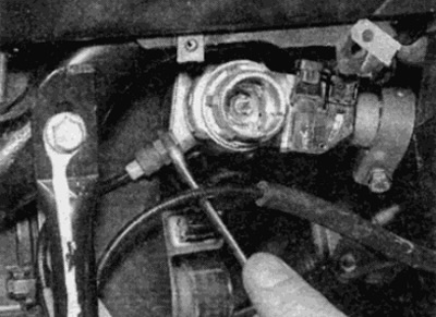
1. Using a small screwdriver, gently pry the lock cylinder cover (see fig. 19.1).
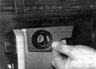
Pic. 19.1. Remove the ignition/steering column trim (Steering wheel removed for clarity)
2. Insert the ignition key and turn the switch to the "I".
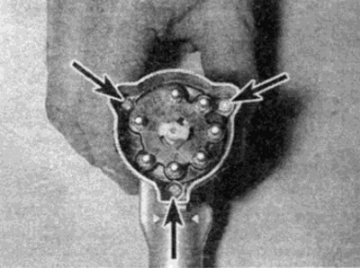
3. Bend a suitable piece of wire with a diameter of 2.0 mm (best to use a welding electrode) into the shape of a letter "P" and file the ends at an angle of 70 (see fig. 9.3).
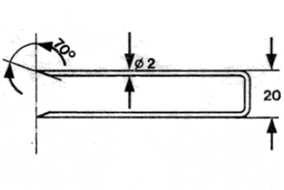
Pic. 19.3. Tool needed to remove the ignition switch (dimensions in mm)
4. Insert a removal tool into the slots on each side of the lock cylinder and push the wire inward to compress the lock cylinder latches.
5. Pull out the lock using the ignition key (see fig. 19.5).
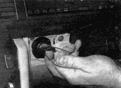
Pic. 19.5. Turn the lock to position "I", then insert the tool and pull the assembly out of the socket
6. Remove the puller and ignition key, then pull the cylinder out of the body (see fig. 19.6).
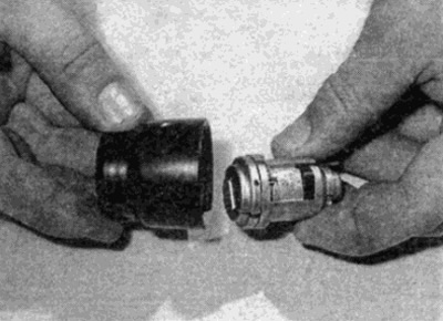
Pic. 19.6. Remove the ignition key and separate the cylinder and housing
Installation
7. To reinstall, insert the lock cylinder into the socket in the steering column, aligning the raised part with the groove in the socket.
8. Install the slotted housing on top of the cylinder. facing towards the steering column.
9. Insert the ignition key, turn it to position "I" and press the cylinder and body into the seat until it stops.
Note: When installing, the edge of the ignition key should point towards the mark on the cover, which indicates that the cover latch is correctly installed.
10. Check the operation of the lock and lock cylinder, then install the facing.
Switch assembly
Removing
11. Disconnect the negative battery terminal.
12. Remove the lock cylinder as described in p.p. 1 to 6, considering that the switch must be in position "I".
13. Remove the lower part of the instrument panel from the driver's side, as described in Chapter 11.
14. Disconnect the connectors from the switch, remembering the installation order and how the wires are routed.
15. On diesel models, mark the alignment between the vacuum hoses and the switch. and disconnect the hoses from the side of the switch housing. On models with an automatic transmission, you will need to unscrew the gear selector lock cable from the lock (see fig. 19.15).
Pic. 19.15. On models with automatic transmission, unscrew the nut and disconnect the lock cable from the lock body
16. Loosen the switch clamp bolt, then press the latch rod and remove the switch from the column (see fig. 19.16. a-c).
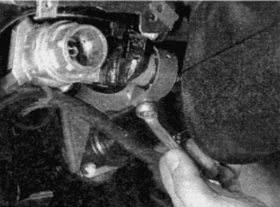
Pic. 19.16, a. Loosen clamp bolt...
Pic. 19.16, b....then press the locking pin...

Pic. 19.16, c....and remove the lock housing from the steering column
Installation
17. Installation is carried out in the reverse order, taking into account the following points:
- A) Make sure the key remains in position "I".
- b) When installing the switch on the steering wheel, make sure that the latch pin is located in the hole in the steering column and securely tighten the clamp bolt.
- V) Make sure the wires are routed correctly and connected securely.
- G) On diesel models, make sure the vacuum hoses are properly connected.
- d) Before installing the lower instrument panel, insert the lock cylinder and check the operation of the assembly.
Ignition switch contact plate
Removing
18. Remove the switch assembly as described in steps 11 to 16.
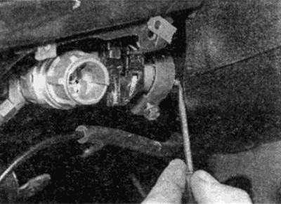
19. Turn away fastening screws and remove a contact plate from the back party of the switch (see fig. 19.19).
Pic. 19.19. Screws of fastening of a contact plate of the switch of ignition
Installation
20. Install the contact plate making sure that the lug fits correctly into the slot in the switch socket. Install the mounting screws and tighten them securely.
21. Install the switch as described in step 17.