
Cars BMW Cars Volkswagen Cars Chevrolet Cars Land Rover Cars Lada Cars Honda Cars Peugeot
English Русский
Български
Беларускі
Український
Српски
Hrvatski
Română
Polski
Slovenský
Magyar
Bookmark News and articles Sitemap Feedback Site search
MercedesMan.ru


A-Class C-Class E-Class G-Class M-Class S-Class Others
190 (W201) (1982-1993) W202 (1993-2000) W203 (2000-2007)
  • Main
  • C-Class
  • W201 (1982-1993)
  • Chassis
  • Steering
  • Steering Tie Rod Ball Joint — Removal and Installation

Steering Tie Rod Ball Joint — Removal and Installation (Mercedes-Benz C-Class W201)

0
Contents: Inner hinge ↡ Outer hinge ↡
Note: A new ball joint nut will be required for installation.


Inner hinge


Removal


1. Apply the parking brake and place chocks under the rear wheels. Raise the front of the vehicle with a jack and support it (see Fig. "Lifting the car and placing it on supports").

2. Clean the inner end of the tie rod and loosen the ball joint clamp bolt. Make a mark on the tie rod and measure the distance from the mark to the center of the ball joint. Record this measurement as you will need it to ensure wheel alignment when installing the joint.

3. Loosen and remove the pivot nut and disconnect the intermediate lever/pitman arm pivot (depending on what is required). If necessary, separate the conical joint pin using a universal puller.

4. Count the exact number of turns required to loosen the ball joint from the tie rod end.

5. Clean the ball joint and threads thoroughly. Replace the ball joint if it is sticking, worn or damaged. Carefully check the condition of the pin cone surface and threads.

Installation


6. Screw the ball joint onto the steering rod the number of turns required for removal. This should ensure that the joint is positioned at the appropriate distance from the mark that was made before removal.

7. Install the ball joint pin onto the idler arm/pitman arm, then install the new mounting nut and tighten it to the specified torque.

8. Tighten the ball joint clamp bolt to the required torque and lower the vehicle to the ground.

9. Check and, if necessary, adjust the front wheel alignment as described in paragraph 31.


Outer hinge


Removal


10. Apply the parking brake and place chocks under the rear wheels. Raise the front of the vehicle with a jack and place it on supports (see "Lifting the car and placing it on supports"). Remove the corresponding wheel.

11. Clean the tie rod ends and loosen the lock nut and ball joint clamp sleeve. Make a mark on the tie rod and measure the distance from the mark to the center of the ball joint. Record this measurement as it will be needed to ensure wheel alignment when installing the joint.

12. Loosen and remove the ball joint nut and disconnect the ball joint from the steering knuckle. If necessary, separate the ball joint pin using a universal puller (see fig. 29.12).
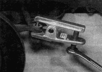
Fig. 29.12. Using a ball joint puller, disconnect the steering rod from the steering knuckle

Fig. 29.12. Using a ball joint puller, disconnect the steering rod from the steering knuckle


13. Count the exact number of turns required to loosen the ball joint from the tie rod end.

14. Thoroughly clean the ball joint and threads. Replace the ball joint if it is sticking, worn or damaged. Carefully check the condition of the pin cone surface and threads.

Installation


15. If necessary, transfer the lock nut to the new tie rod ball joint.


16. Screw the ball joint onto the steering rod to the same number of turns as when removed. This should ensure that the joint is positioned at the appropriate distance from the mark that was made before removal.

17. Install the ball joint pin onto the steering knuckle, then install the new mounting nut and tighten it to the required torque (see fig. 29.17).
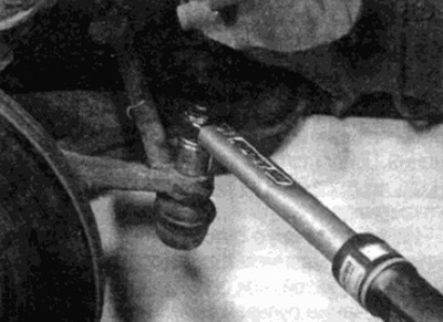
Fig. 29.17. When installing, screw on a new fastening nut and tighten it to the required torque

Fig. 29.17. When installing, screw on a new fastening nut and tighten it to the required torque


18. Install the wheel and lower the vehicle to the ground. Tighten the wheel bolts to the required torque.

19. Check and, if necessary, adjust the front wheel alignment as described in paragraph 31. After this, tighten the clamping ring to the required specification torque and tighten the lock nut securely.
This article is available at: russian, bulgarian, belarusian, ukrainian, serbian, croatian, romanian, polish, slovak, hungarian
The article has been verified: Lukyanov Nikita Ilyich
Share with friends:
◀ Previous
C-Class 190 (W201) / Steering
Next ▶

Intermediate steering arm — removal and installation
Longitudinal steering rod — removal and installation
Steering shock absorber — removal and installation
Power Steering — Air Bleed
Power Steering Pump — Removal and Installation
Steering rod — removal and installation
Wheel and steering angles — basics
More similar articles for repairing other models

☛ Ball joint caps — check Mercedes W168 (1997-2004)
☛ Checking mudguards and ball joint play Mercedes W210 (1996-2002)
☛ Checking the condition of suspension and steering components Mercedes W463 (1999-2019)
☛ Removal and installation of steering knuckle, replacement of ball… Mercedes W163 (1997-2005)
☛ Dust boot of the articulated joint of the connecting rod and steering… Mercedes W126 (1979-1991, petrol)
☛ Replacing the ball joint Mercedes Sprinter (1995-2000, diesel)
Link in different formats to this article
Comments and feedback from visitors
No comments yet


How much will 10 + 27 ?


W203 (2000-2007) 
  • General information
  • Introduction to guide
  • User manual
  • Maintenance
  • Power unit
  • Gasoline engines
  • Diesel engines
  • Cooling system
  • Ventilation and heating
  • Supply system
  • Injection system (gasoline)
  • Injection system (diesel)
  • Exhaust system
  • Ignition and control system
  • Charge and launch systems
  • Transmission
  • Mechanical gearbox
  • Automatic gearbox
  • Clutch and drive shafts
  • Differential
  • Chassis
  • Brake system
  • Car suspension
  • Steering
  • Body
  • Exterior (external elements)
  • Interior (internal elements)
  • Electrical equipment
  • Equipment and devices
  • Lighting system
  • Electrical diagrams (2000)
  • Electrical diagrams (since 2001)
W202 (1993-2000) 
  • General information
  • User manual
  • Driving a car
  • Car care
  • Maintenance
  • Power unit
  • Gasoline engines
  • Diesel engines
  • Lubrication system
  • Cooling system
  • Heating and ventilation
  • Ignition system
  • Fuel system
  • Injection system (gasoline)
  • Injection system (diesel)
  • Exhaust system
  • Transmission
  • Clutch
  • Car gearbox
  • Chassis
  • Suspension, wheels and tires
  • Steering
  • Brake system
  • Body
  • Exterior (external elements)
  • Interior (internal elements)
  • Doors and windows
  • Electrical equipment
  • Equipment and devices
  • Power devices
  • Lighting system
  • Electrical circuits
190 (W201) (1982-1993) 
  • General information
  • Introduction to the guide
  • Operation and care
  • Maintenance (gasoline)
  • Maintenance (diesel)
  • Troubleshooting
  • Power unit
  • Petrol engine I4
  • Petrol engine V6
  • Diesel engines
  • Engine overhaul
  • Cooling and heating
  • Power system (carburetor)
  • Injection system (gasoline)
  • Injection system (diesel)
  • Exhaust system
  • Charge and start system
  • Ignition system (I4)
  • Ignition system (V6)
  • Diesel heating system
  • Transmission
  • Clutch
  • Mechanical gearbox
  • Automatic gearbox
  • Cardan shaft and axle shafts
  • Chassis
  • Brake system
  • Car suspension
  • Steering
  • Body
  • Exterior (external elements)
  • Interior (internal elements)
  • Doors, locks and windows
  • Electrical equipment
  • Equipment and devices
  • Electrical circuits
 
MercedesMan.ru © 2017–2026 · Mobile version · Read about Mercedes · Sitemap: EN BG BY UA RS HR RO PL SK HU · Feedback · Site search · Bookmark A-Class (W168) · C-Class (W201) · C-Class (W202) · C-Class (W203) · E-Class (W123) · E-Class (W124) · E-Class (W210) · G-Class (W463) · M-Class (W163) · S-Class (W116, petrol) · S-Class (W126, petrol) · S-Class (W140) · S-Class (W220) · Sprinter · Vito 1 · Vito 2 · Vario 814D ·
 
We only use cookies without which some of the site's features may not be available.