



Contents: Removal ↡ Installation ↡
Removal
1. Remove the front wheel.
2. Unscrew the locking screw screwed into the brake shield. Loosen the axial nut (7a) of the ball joint support joint.
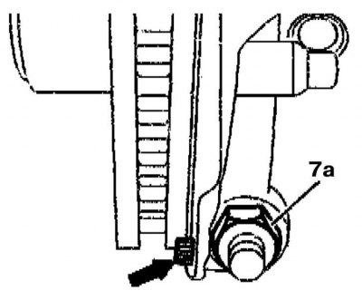
3. Screw the thrust element (044b) onto the axle of the ball joint support joint, pull the brake disc with the shield outward and, using puller (044) No.140 589 09 33 00, separate the support joint from the steering knuckle.
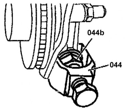
4. Unscrew the hinge nut from the lever side.
5. Proceeding in a similar manner, release the ball joint from the suspension arm.
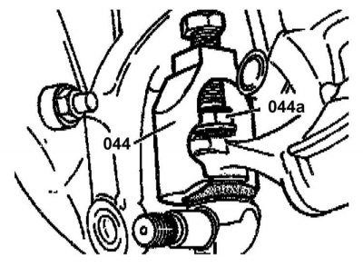
6. If necessary, clean the conical elements of the hinge assembly.
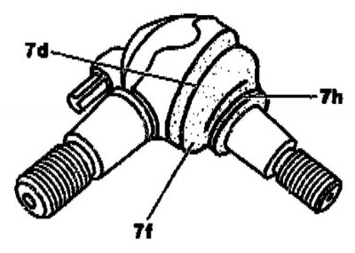
7. Assess the condition of the protective cover (7f) and the wire clamps (7d and 7h) that secure it. If necessary, perform the necessary repairs or replace the faulty components/hinge assembly.
Installation
Installation is carried out in reverse order.
Tighten the support mounting self-locking nuts to the required torque (to the steering knuckle: 140 Nm, to the lever: 100 Nm). Tighten the locking screw on the brake shield with a force of 22 Nm, on the brake disc – with a force of 10 Nm.