
Removing
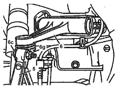
1. Separate from upper arm (6) rounded fist (5), - if necessary, use the puller No. 140 589 02 31 00. Try to prevent the brake hose and electrical wiring from straining.
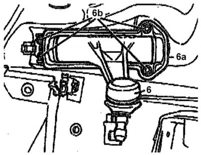
2. Remove nuts (6b) fastenings of the holder of the bearing axial assembly (6a) to the frame.
Installation
1. Install in reverse order of removal of components.
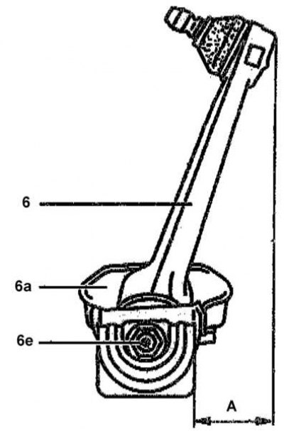
2. After installing the lever on the frame, tighten the nuts securing the axle part with a force of 50 Nm, then loosen the axle self-locking nut (6e) and adjust the position of the lever so that distance A is 63 mm. Tighten the self-locking nut to 120 Nm.
3. Tighten the self-locking nut of the lever to the steering knuckle with a force of 125 Nm.