



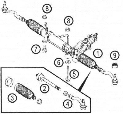
VN 6.001 1. Steering gear housing; 2. Steering rod; 3. Steering rod boot; 4. Tie rod end; 5. Bolt; 6. Washer; 7. Bolt; 8. Nut; 9. Nut
Vito Viano vehicles use a rack-and-pinion steering mechanism with hydraulic booster. The rack is combined with the hydraulic cylinder rod.
The housing of the steering gear drive shaft contains a hydraulic distributor valve system, which acts as a hydromechanical tracking system. This tracking system operates the hydraulic power steering cylinder in strict accordance with the steering wheel movements.
The rack is connected to the steering knuckles of the front wheels by means of two steering rods.
At the inner end of the steering rod there is a spherical joint, the body of which is screwed into a threaded hole located in the end of the rack. At the outer end of the tie rod there is a spherical joint, commonly called the tie rod end. The tie rod end is screwed onto the threaded end of the rod with its threaded hole and secured with a lock nut. It is also possible to adjust the length of the steering rod, which is used when setting the toe-in of the front wheels.
Removal and installation the steering gear
1. Set the steering wheel to position.
2. Remove the air filter housing, moving straight ahead.
3. Drain the oil from the power steering tank.
Then remove any remaining oil from the steering gear through the return hose by alternately rotating the steering wheel from one extreme position to the other.
4. Unscrew the bolts (1) (drawing VN 6.002).
5. Support the engine without lifting it.
6. Disconnect the right and left steering tips (5) from the steering knuckles (drawing VN 6.003).
7. Remove the engine compartment protective tray.
8. Unscrew the nuts (7 and 8).
9. Remove the clamps (9).
10. Disconnect the hydraulic pipes (11 and 12).
Article borrowed from the web portal mercedesman
11. Disconnect the steering shaft cardan joint (13) from the steering gear (14).
12. Unscrew the bolts (16), paying attention to the different lengths of the bolts.
13. Support the subframe (17).
14. Unscrew the bolts (18).
15. Remove the steering gear through the left side of the vehicle. Do not turn the steering gear.
16. Installation is carried out in reverse order.
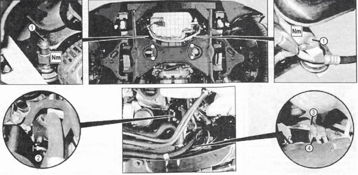
VN 6.002 1. Bolts 2. Hydraulic tube 3. Hose 4. Clamp
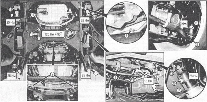
VN 6.003 5. Tie rod end; 6. Nut; 7. Nut; 8. Nut; 9. Clamp; 10. Bolt; 11. Hydraulic tube; 12. Hydraulic tube; 13. Steering shaft cardan joint; 14. Steering mechanism; 15. Bolt; 16. Bolts (please note the different lengths of the bolts); 17. Front subframe; 18. Bolts